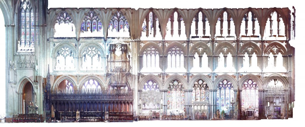
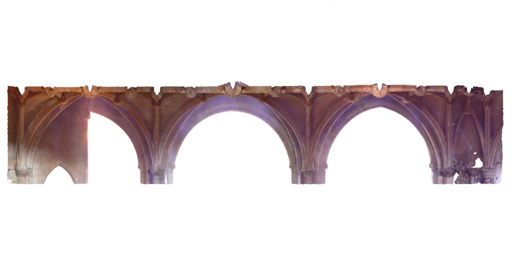
Whilst it is not known exactly when the building of Hotham’s Choir began, it is widely assumed to be some point between 1322 and 1328. Construction appears to have progressed in several phases, with numerous changes in design along the way. Furthermore, some minor elements of the previous twelfth-century choir appear to have been retained, making it difficult to interpret its design process.
The vaults in the central vessel and the north choir aisle were both erected in the final phase of construction, probably dating c. 1335 onwards. Both the appearance and geometry of these two vaults is quite different, demonstrating how variable vault design could be within a single site, even during the same time frame.
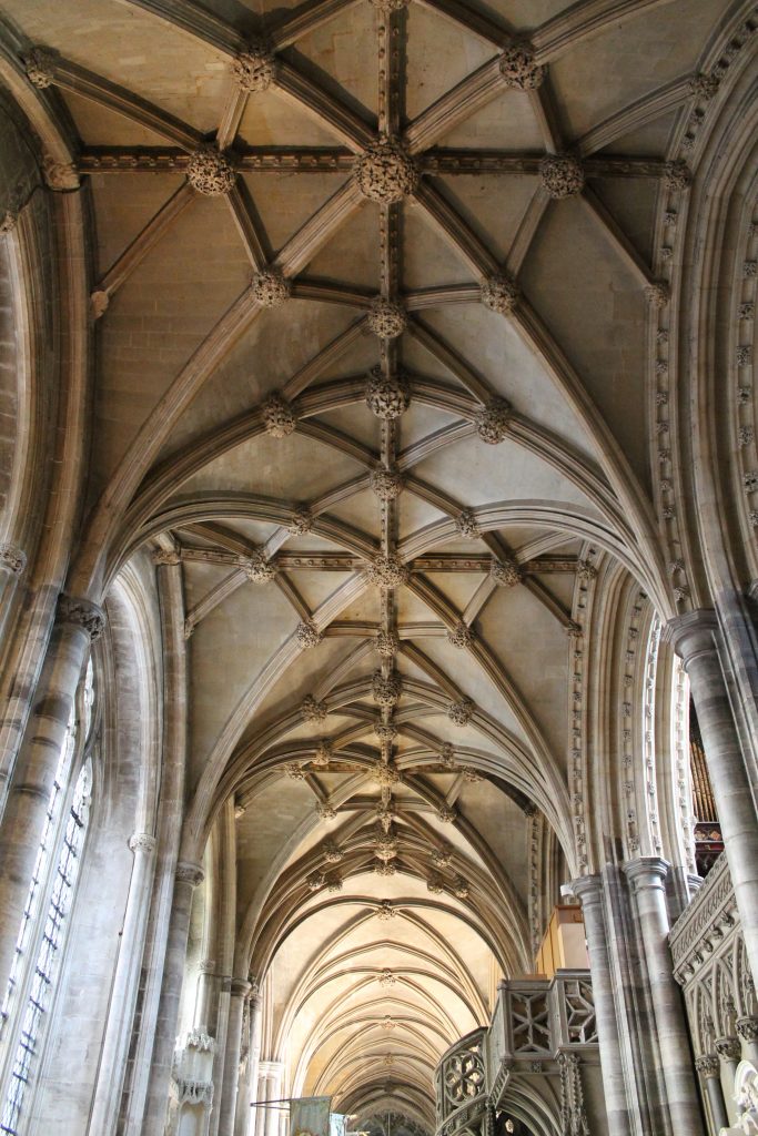
High Vault
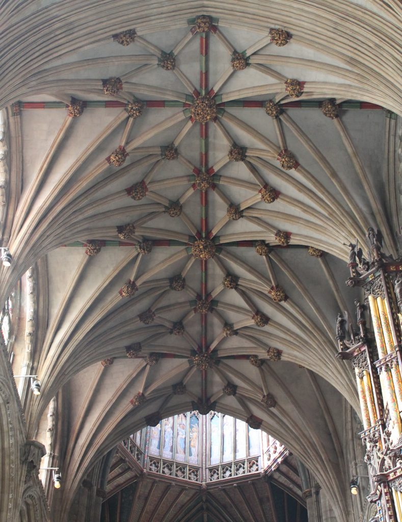
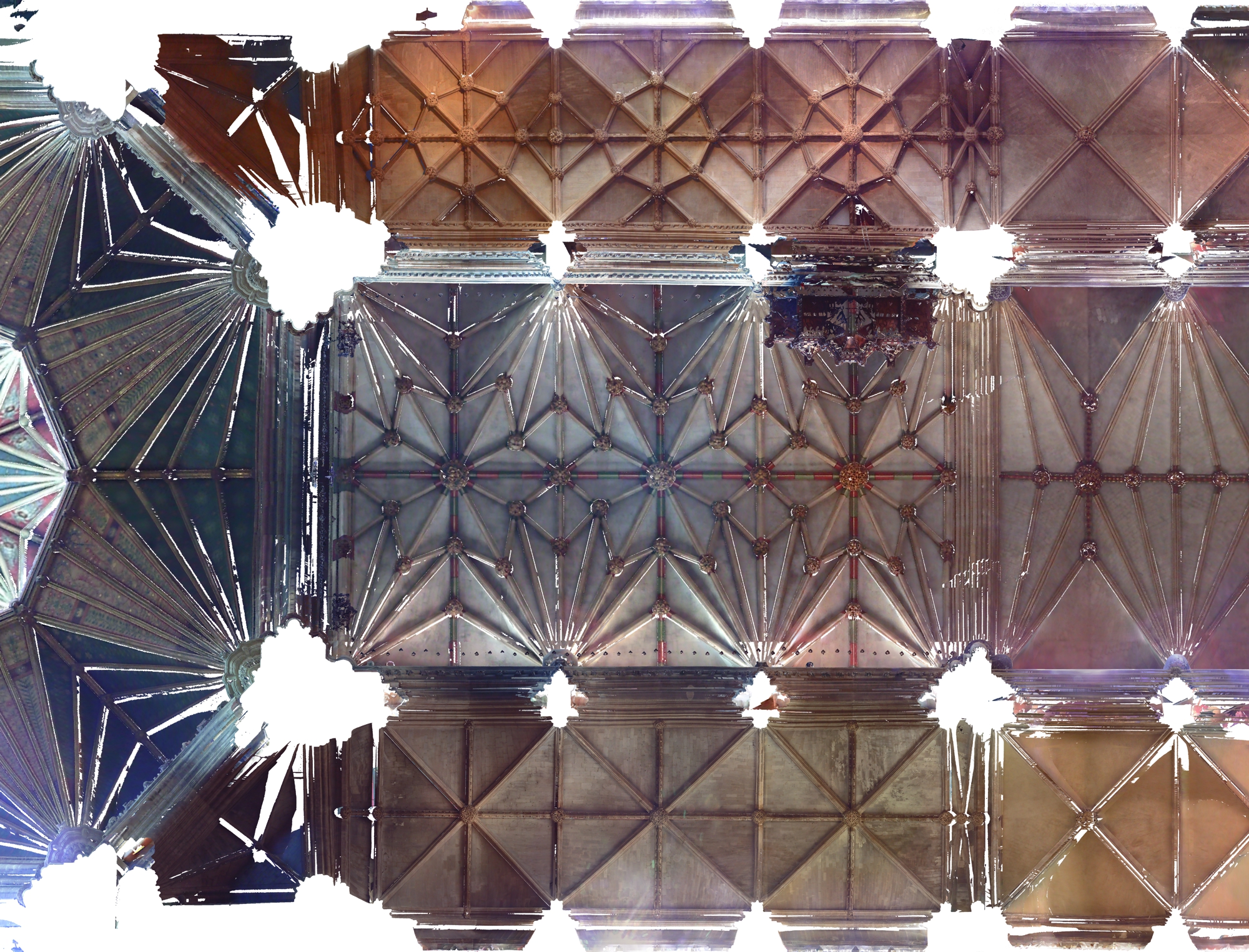
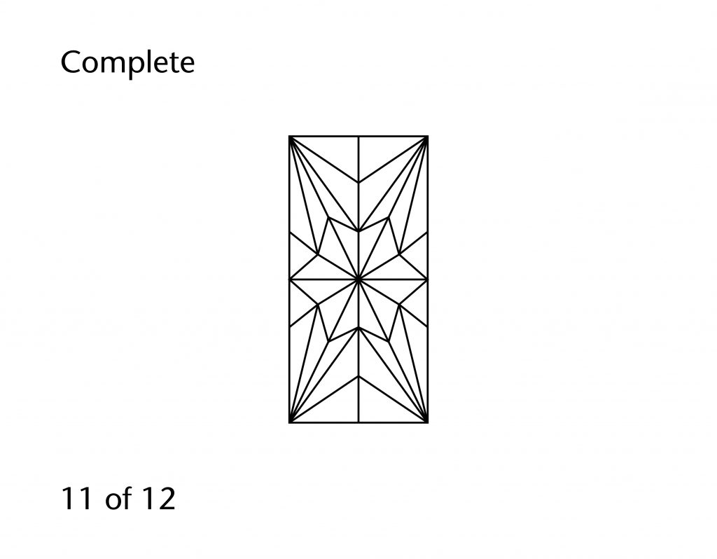
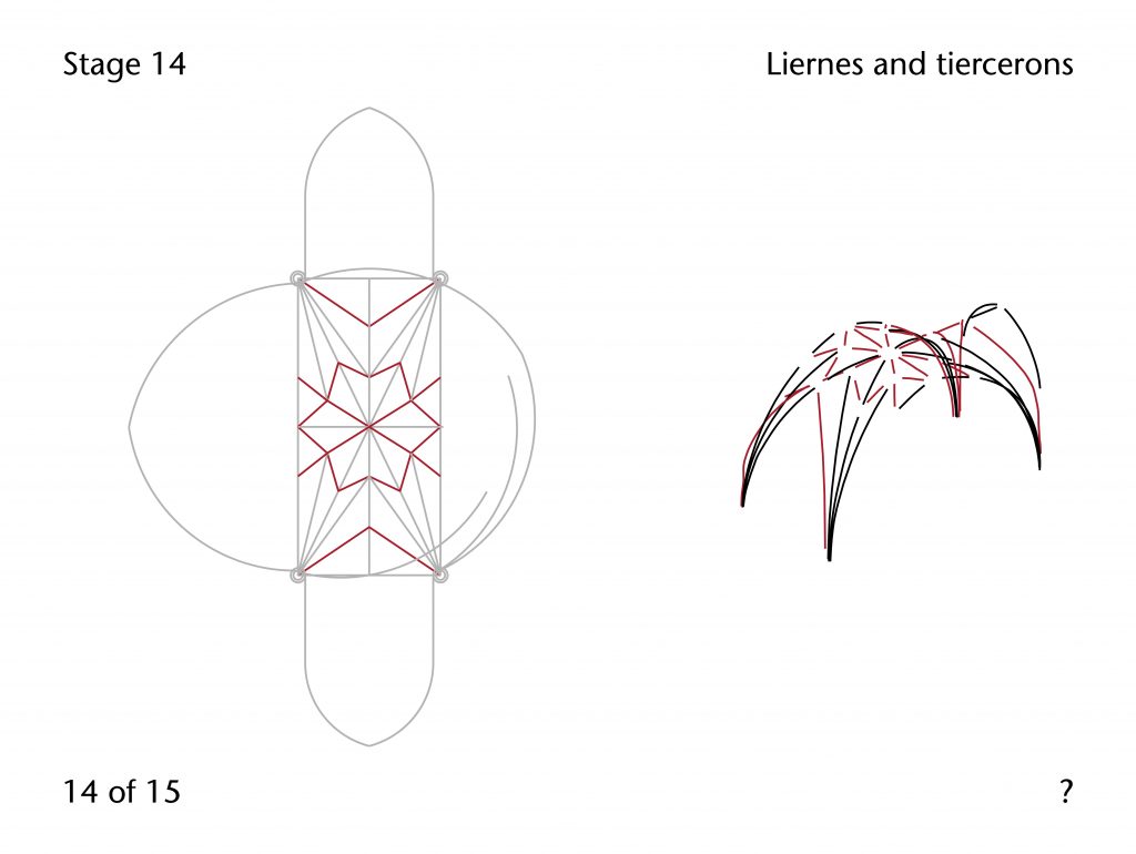
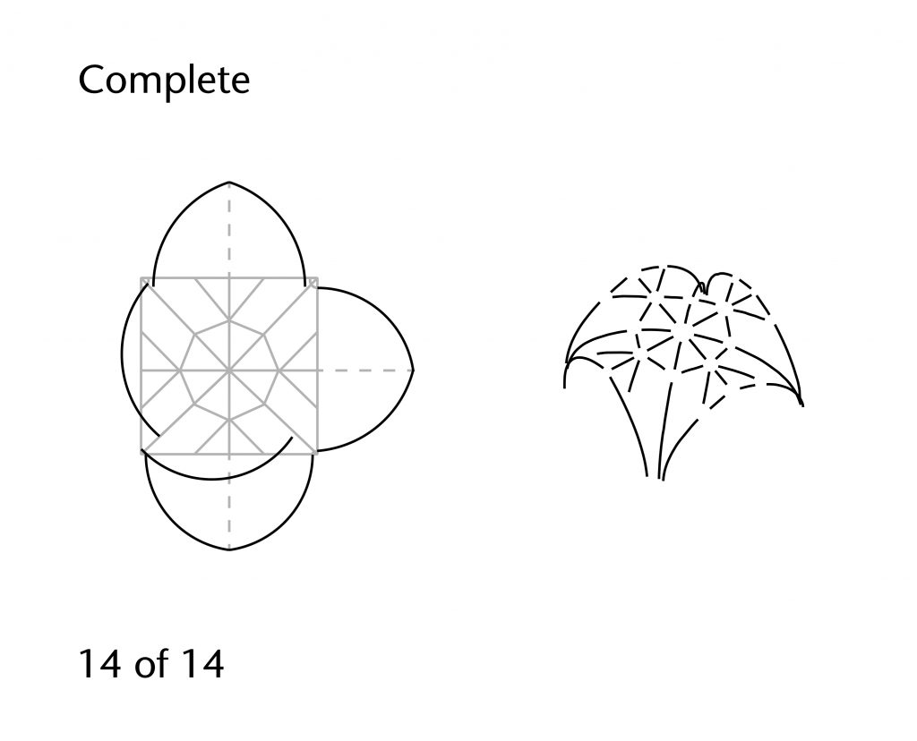
The high vault of Hotham’s Choir consists of a complex pattern of ribs articulated by a stellar arrangement of liernes. Interpreting the geometry of the vault is made difficult by the complex construction history of the choir below, as this has resulted in a number of irregularities in its design and execution. The measurements we have taken are highly variable, necessitating the careful study of each bay individually. Differences in design between the north and south walls have resulted in further variation within the bays of themselves, with different geometrical techniques being used for the ribs on the north and south sides of the vault.
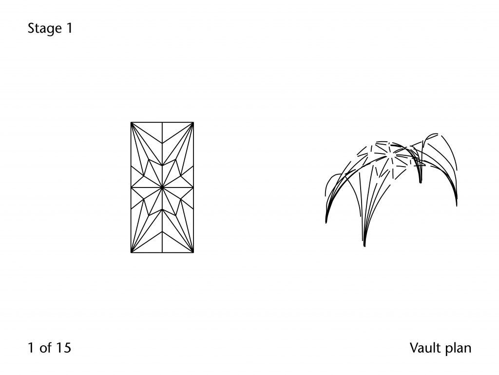
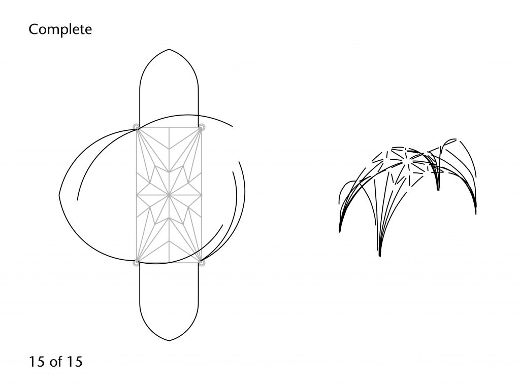
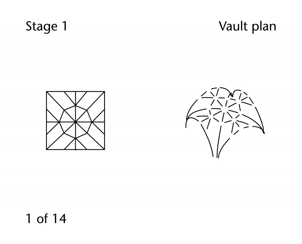
Vault Plan
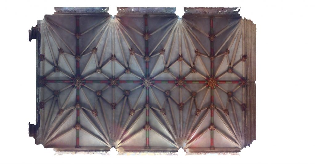
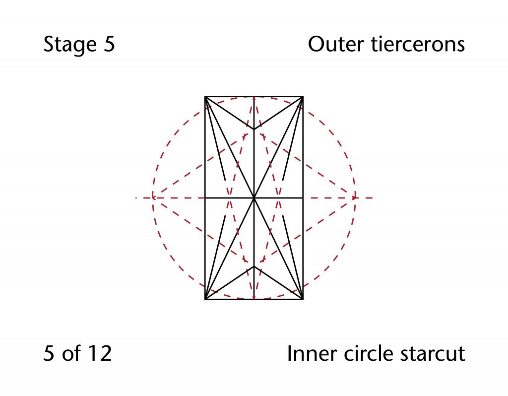
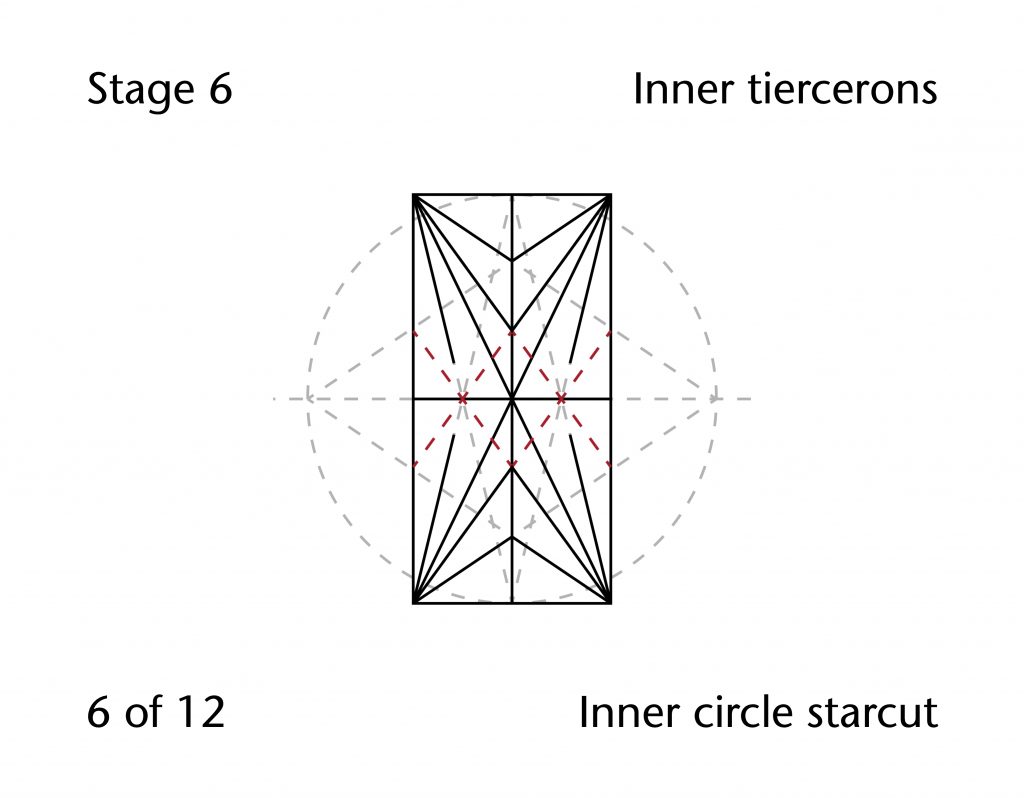
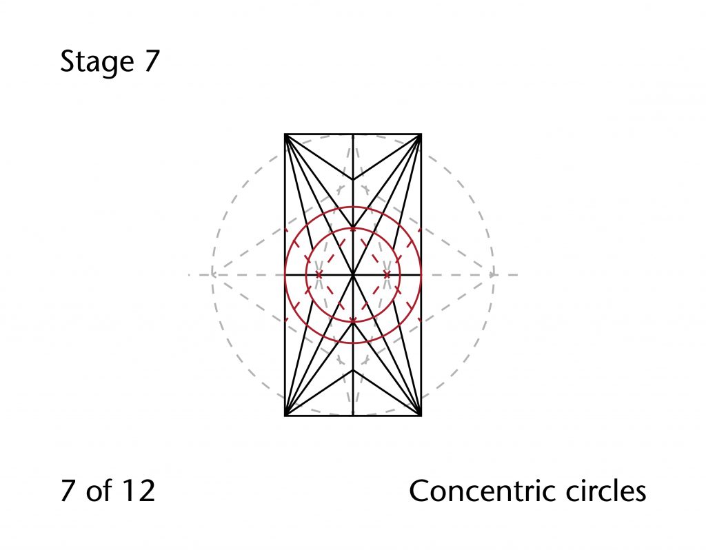
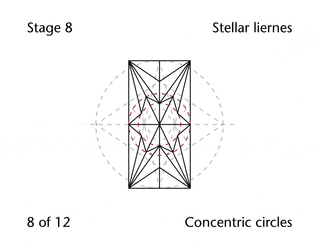
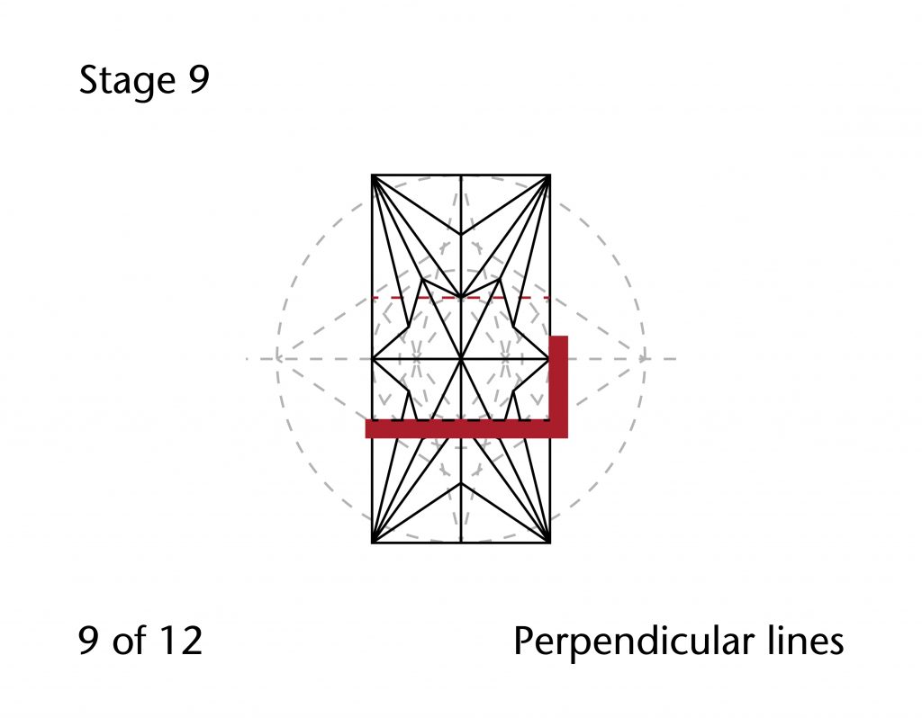
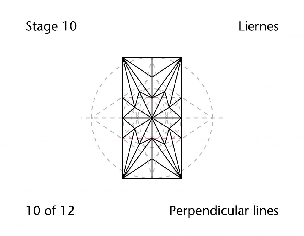
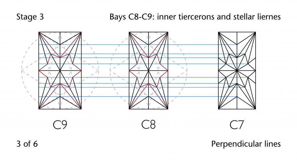
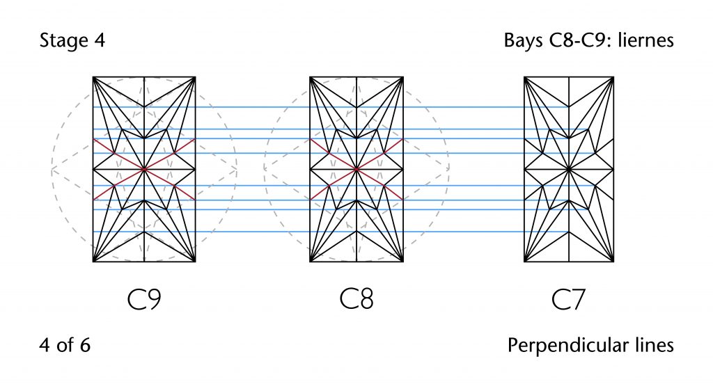
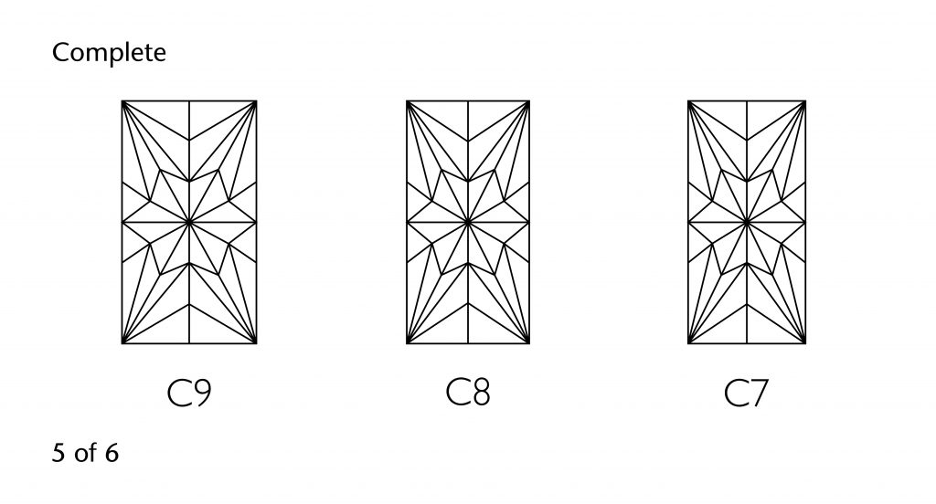
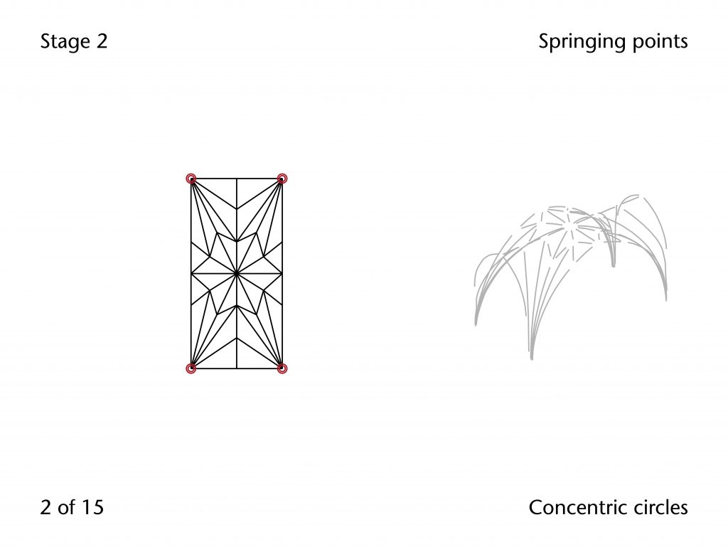
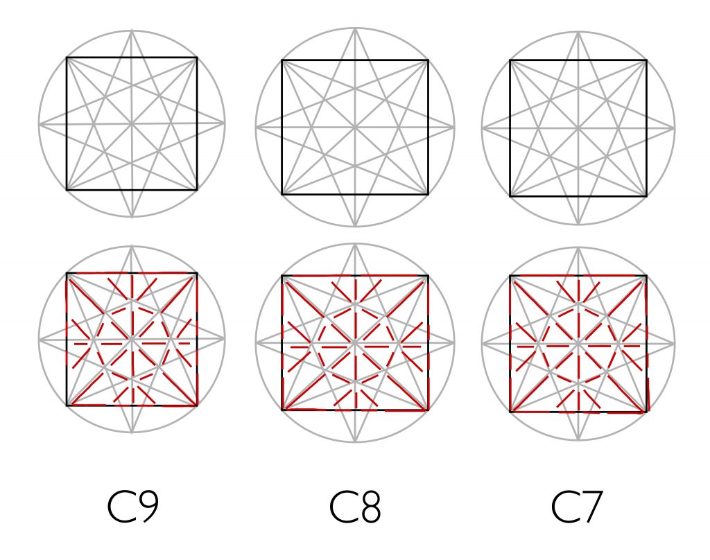
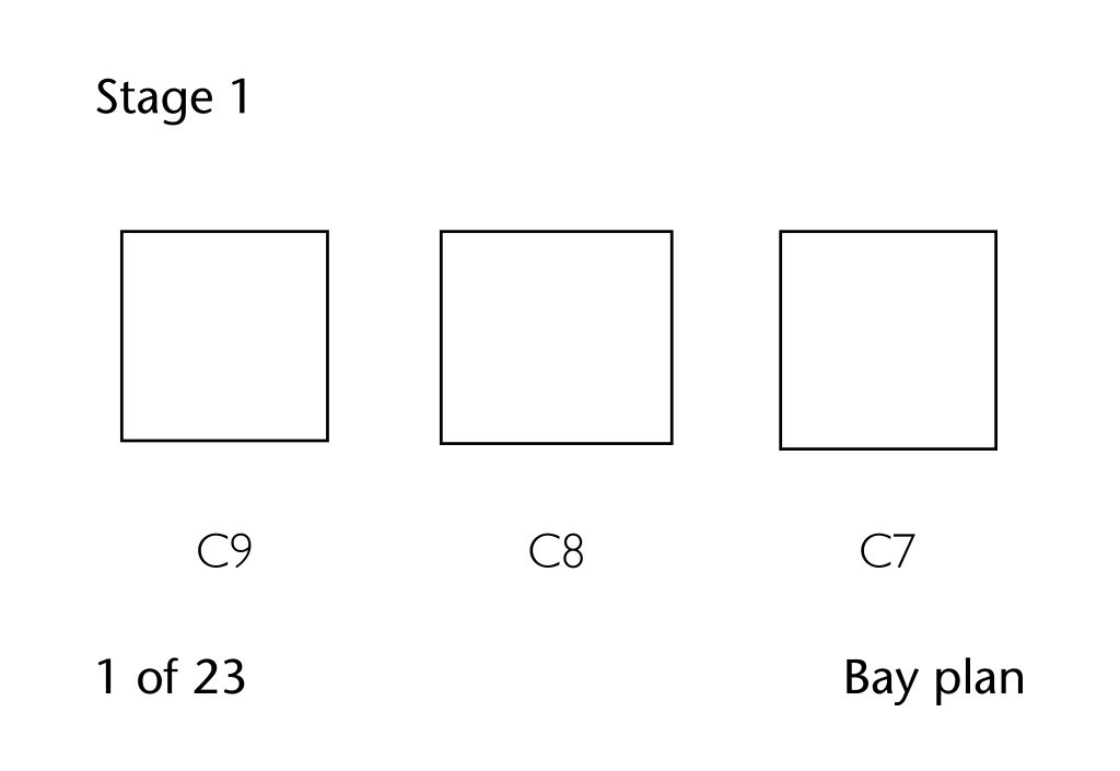
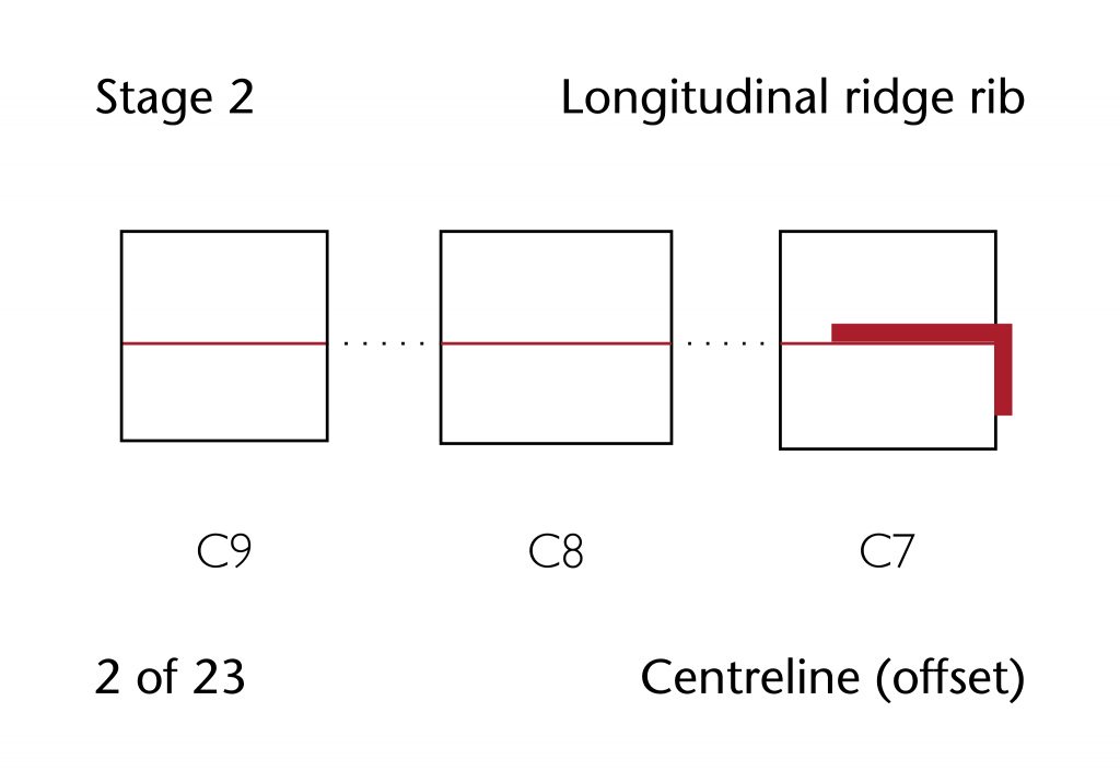
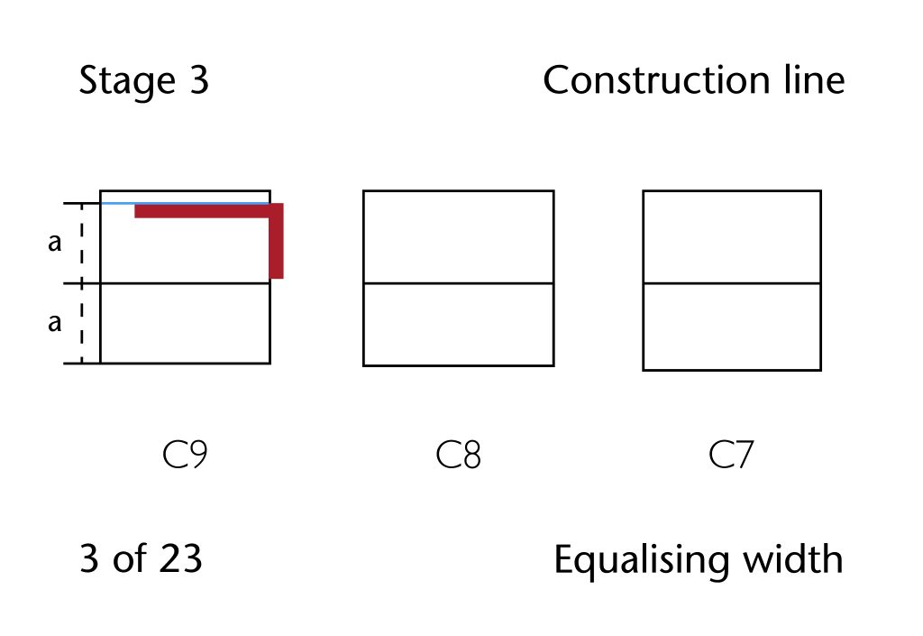
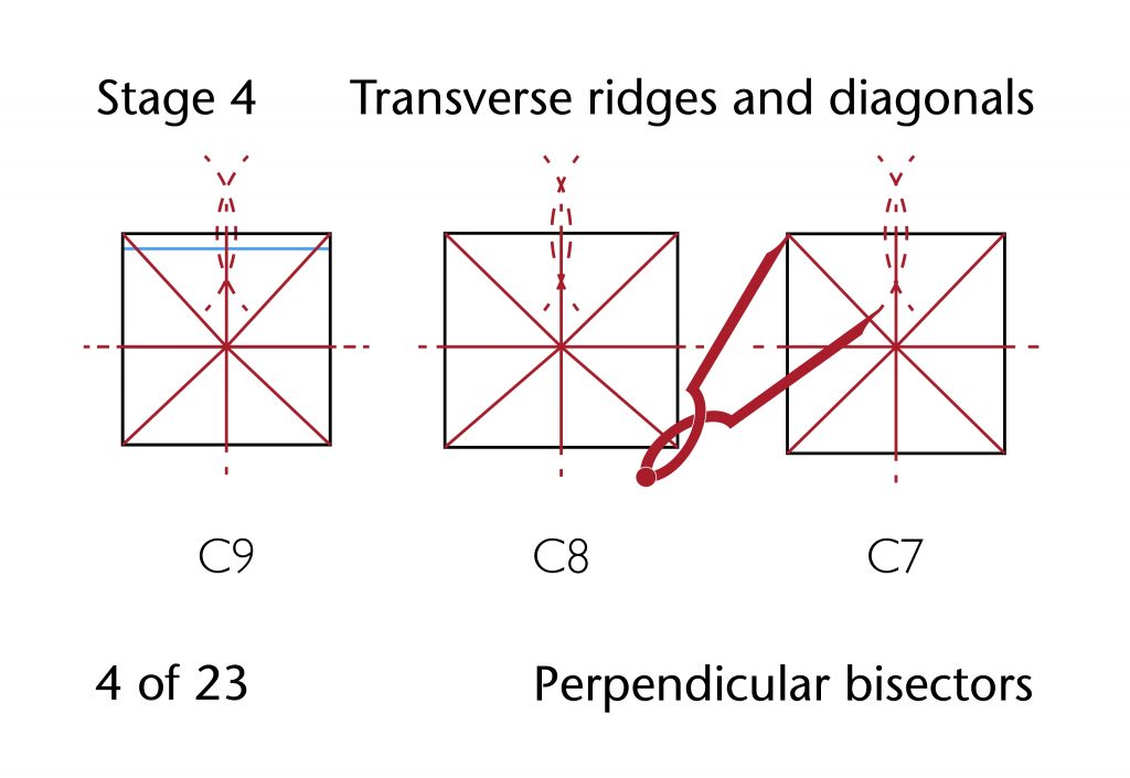
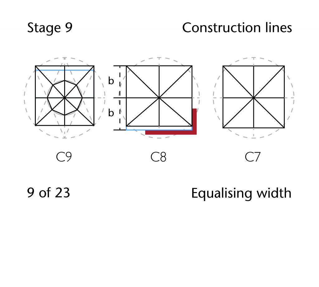
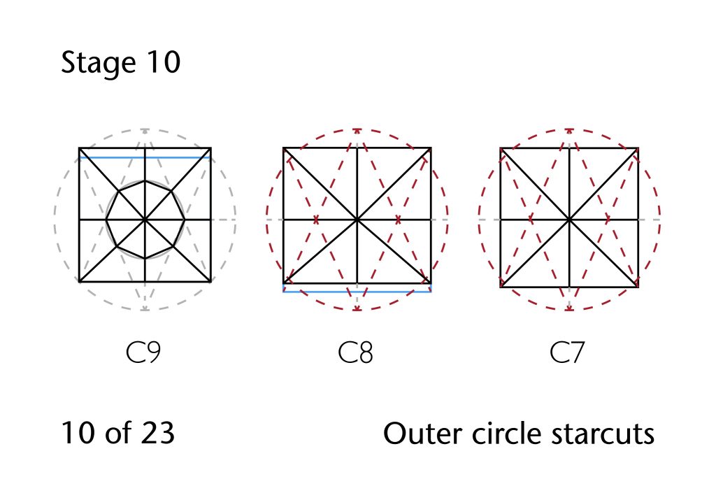
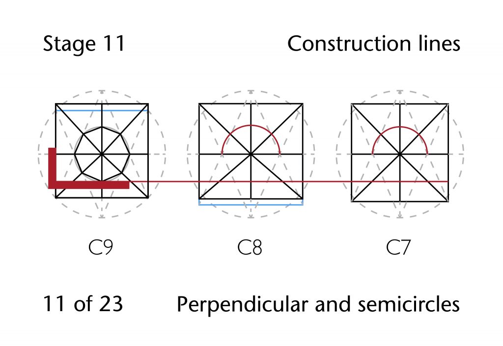
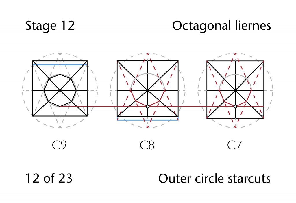
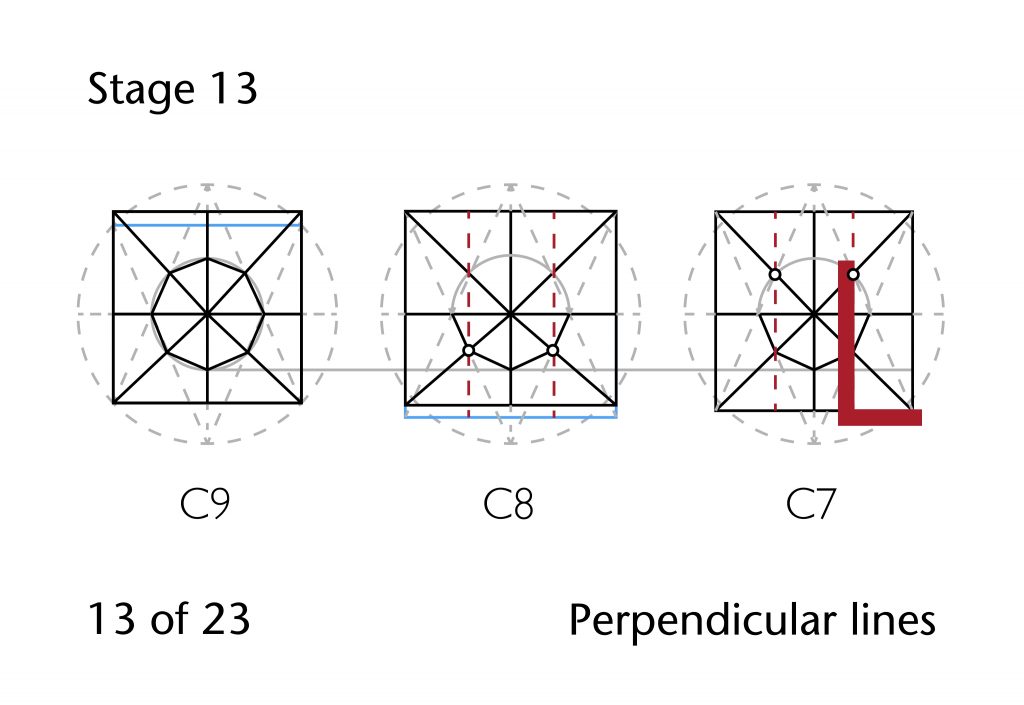
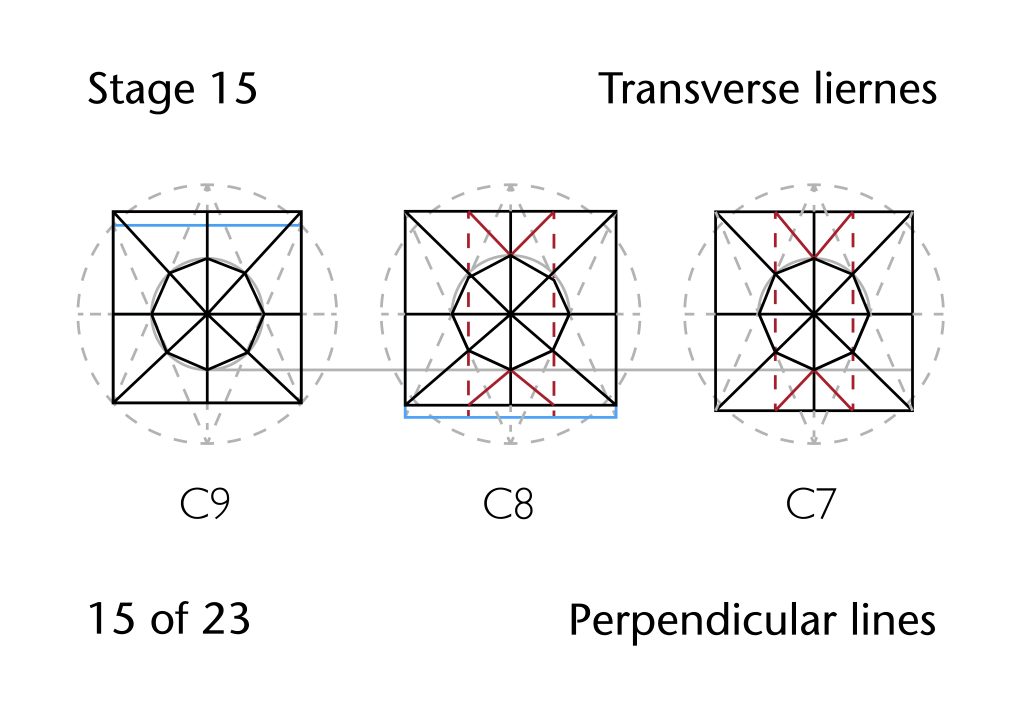
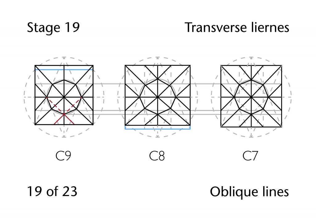
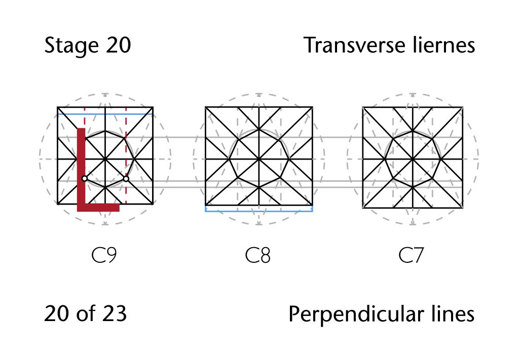
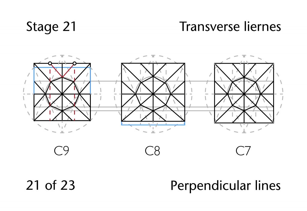
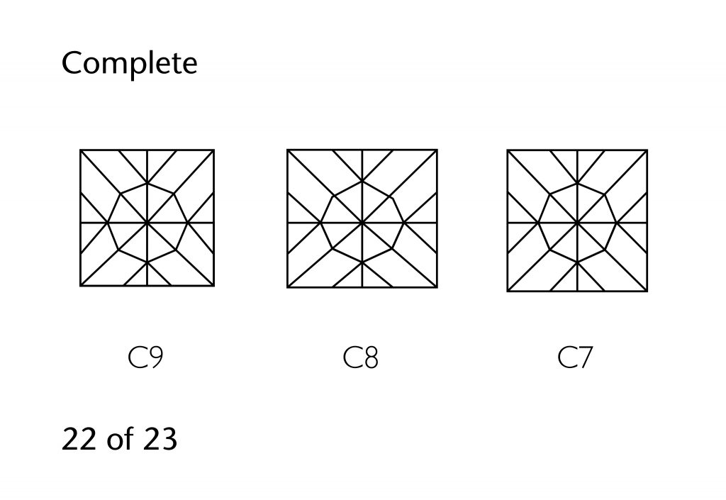
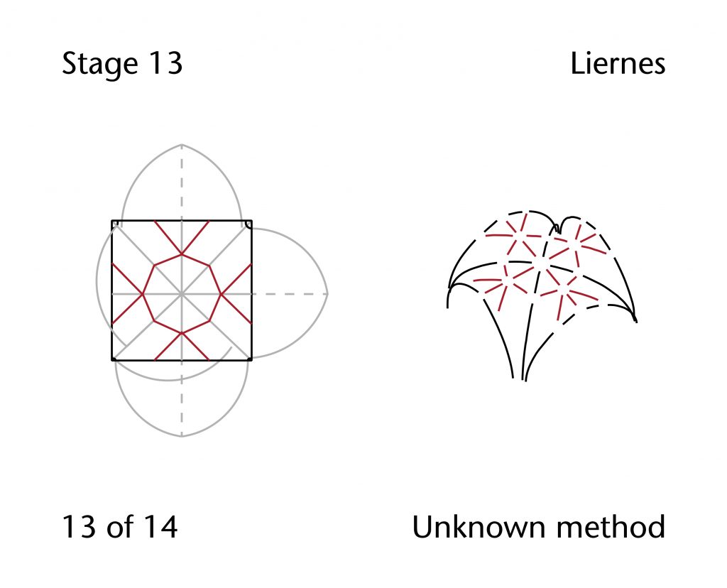
Despite the difficulties presented by the traced data, it is nevertheless possible to propose a tentative hypothesis for the vault’s design process. The vault appears to have been laid out using the geometrical method we have called the inner circle starcut. Firstly, the ridge lines of the bay would be established using perpendicular bisectors through the midpoints of the sides of the bay. The diagonal ribs would then be drawn in by joining corner to corner, providing all the lines and points necessary for the designer to draw their starting figure. A circle would have been drawn with a diameter equal to the vault’s transverse span, centred on the midpoint. This would be used as the basis for drawing an inner circle starcut, allowing the outer sets of tiercerons to be defined. Further lines would be used to define the inner set of tiercerons, and the resulting points of intersection would be used to draw the circles necessary for defining the stellar pattern of liernes. Once the star pattern had been drawn in, the inner set of tiercerons would be used to draw further lines perpendicular to the transverse sides of the vault. This allowed the springing points for the final set of liernes to be located, resulting in a finished vault design.
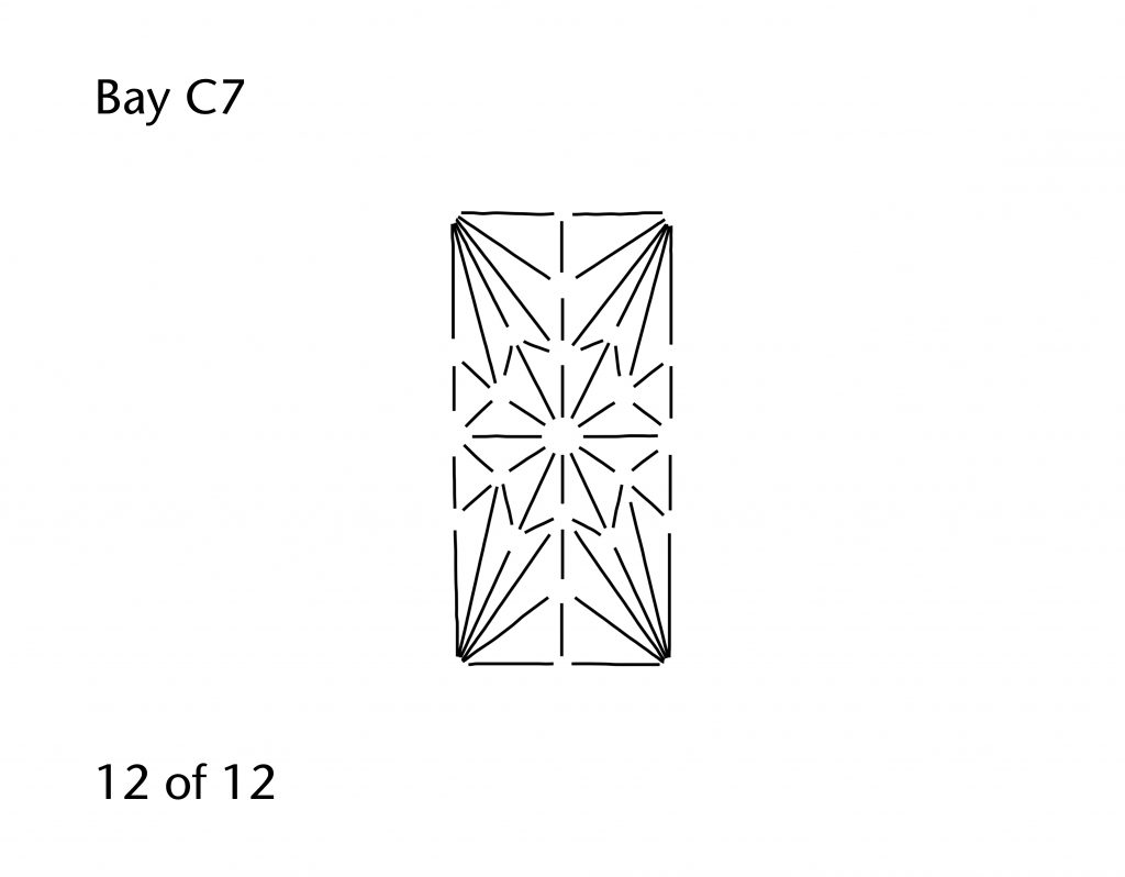
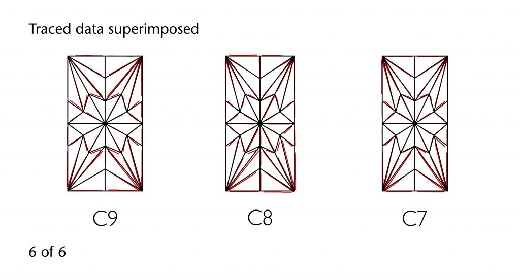
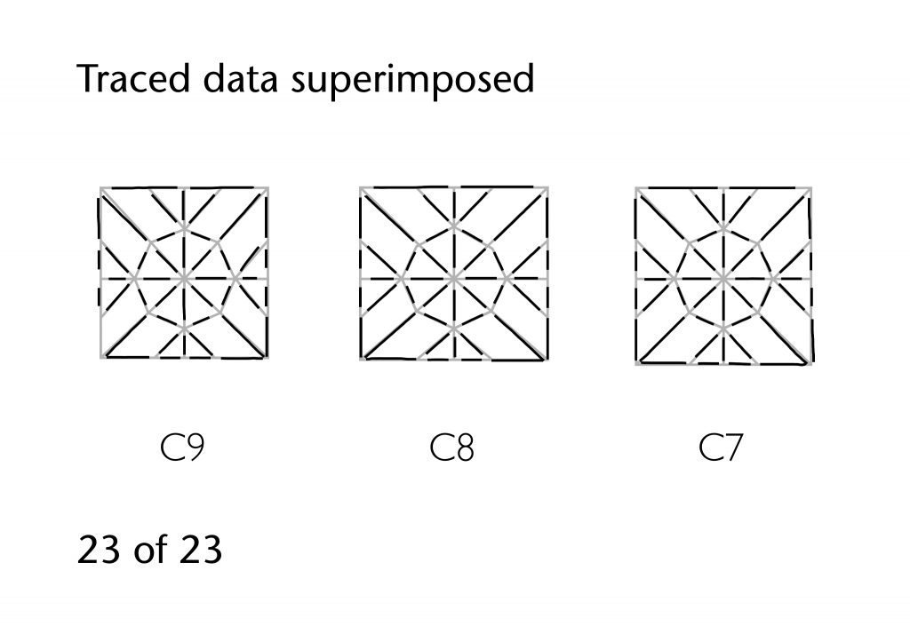
Though such a process does provide a reasonable approximation for the vault plan at Ely, when the hypothesis is compared to the traced the results are not as close as might be desired. Whilst the diagonals, ridge ribs and tiercerons provide a fairly good match for all three bays in the choir, the traced liernes invariably depart considerably from the predicted versions in the hypothesis. This is especially noticeable in bay C9, where the hypothesis results in a far thinner set of east and west points for the central star than can be observed in the traced data.
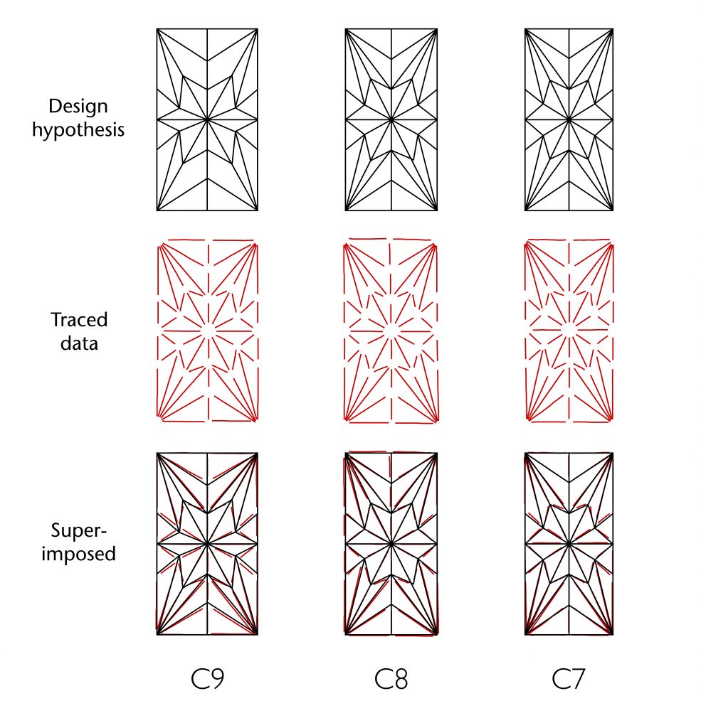
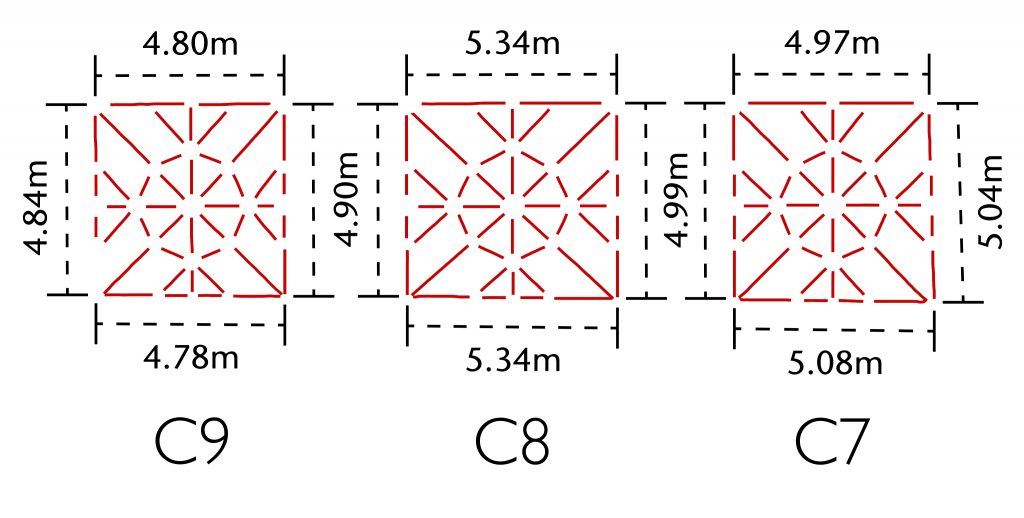
The principal reason for this disparity is that all three bays have different lengths. If a regular starcut had been used, the proportional structure of the vault along the transverse side would have remained identical from bay to bay, regardless of their longitudinal dimensions. However, the decision to employ an inner starcut meant that the divisions used to create the vault’s pattern were directly proportional to the length of the bay. This results in a significant change in proportions when the hypothesised design process is applied to each successive bay. With the resulting disparity between hypothesis and traced data, it is probable that some alternative method was used to ensure consistency throughout the vaulting.
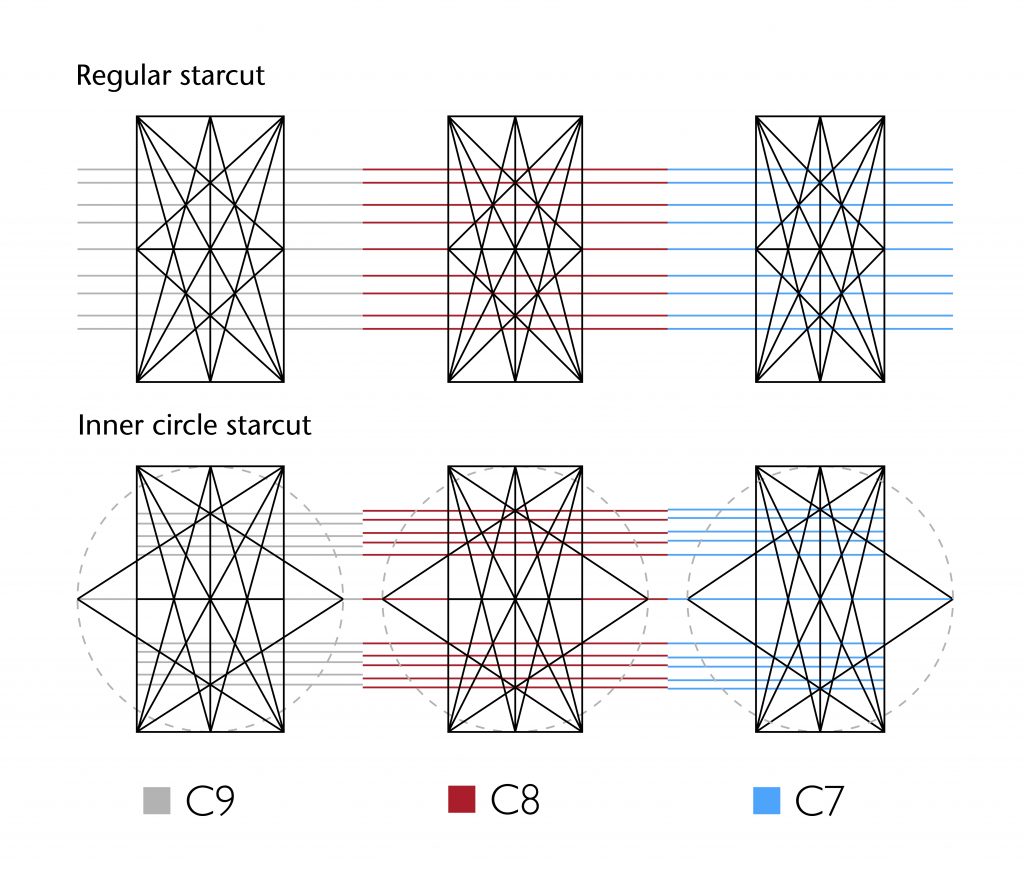
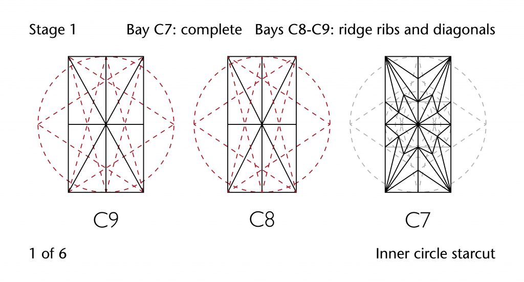
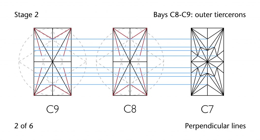
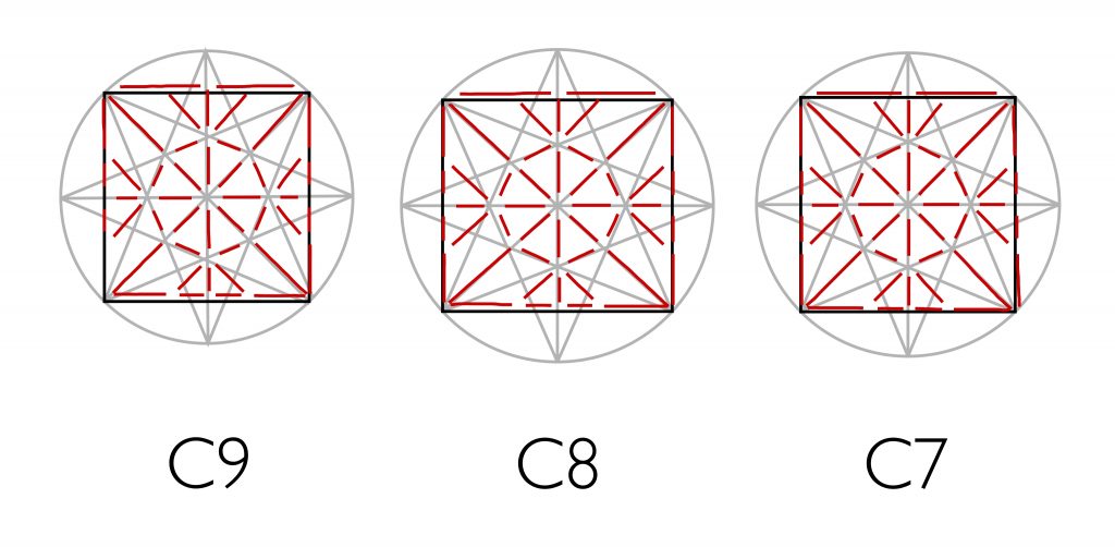
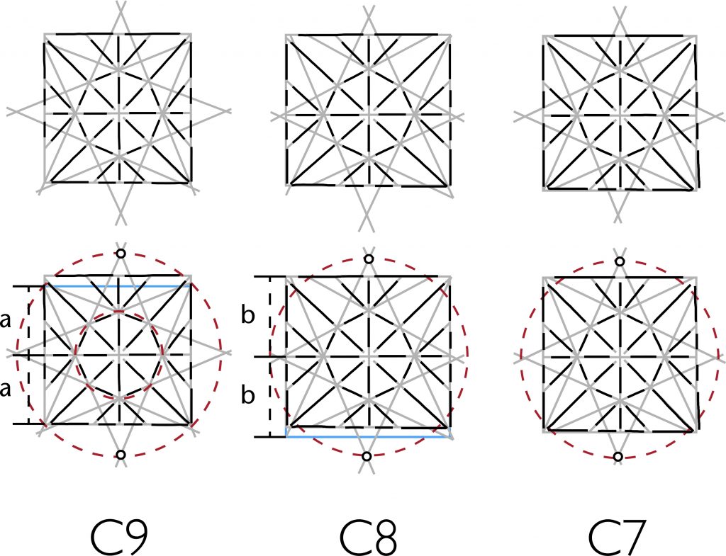
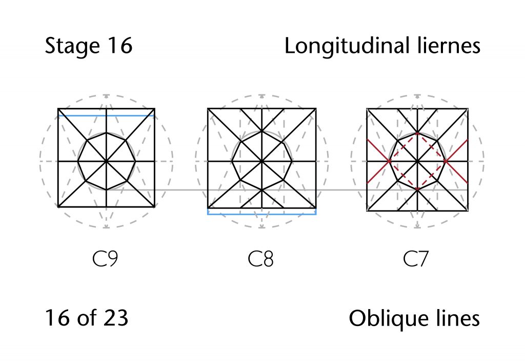
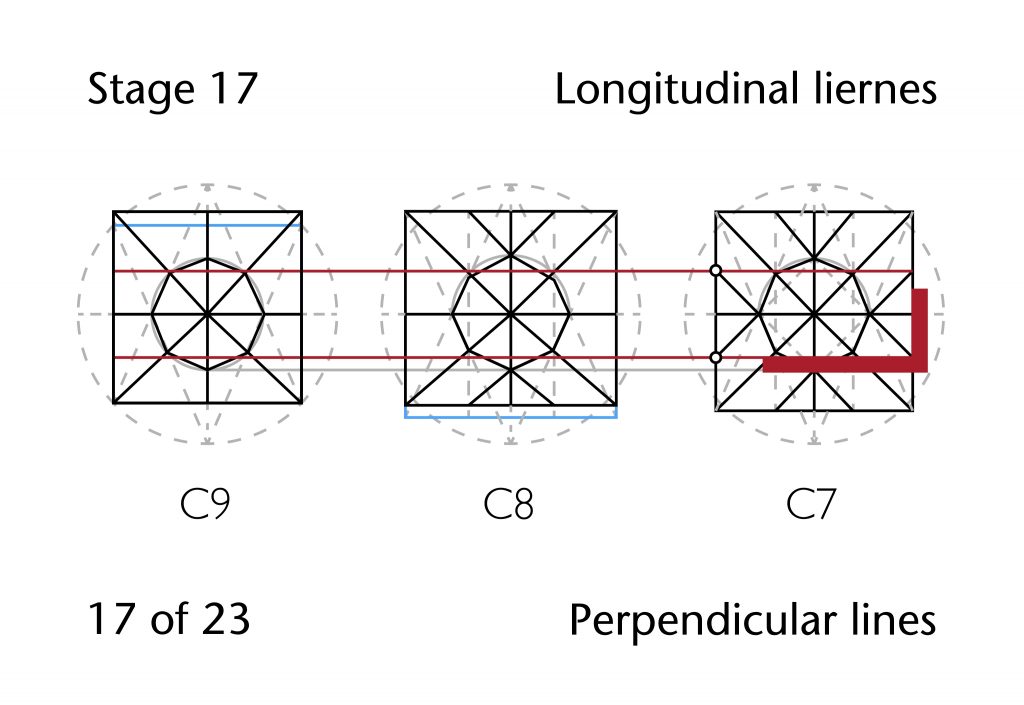
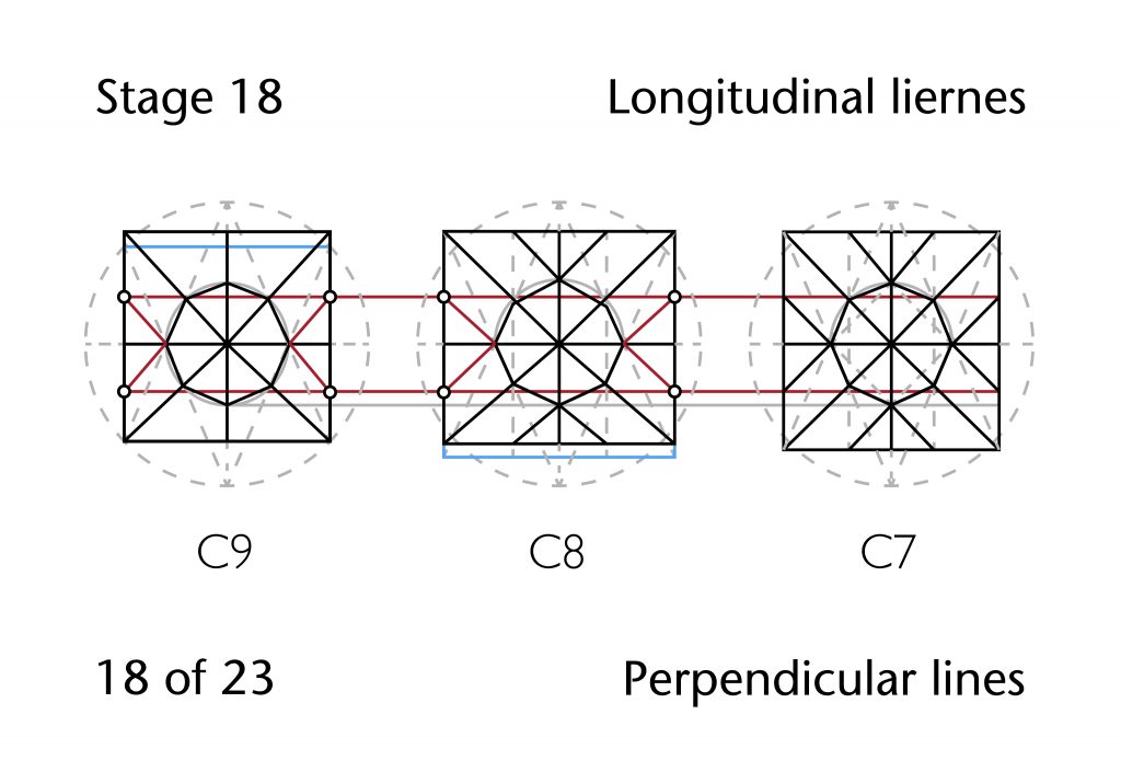
The most likely possibility is that the designers adopted some kind of hybrid method, whereby a single bay was used to establish the pattern and the proportions transferred to the remaining bays using perpendicular lines. The closest visual correlation between hypothesis and traced data is provided by bay C7, making this a likely candidate as the starting bay. However, it is equally possible that bay C8 was used. Whatever the case, the first bay would be constructed as described above, using the inner circle starcut to lay out the ribs of the vault. Whilst the inner circle starcut would be set out for the other two bays, it would not be used to set out the ribs immediately, with only the diagonals and ridge ribs being defined at the outset. The positions of the tiercerons and liernes would be located by transposing their transverse position directly from the plan of bay C7. This would have involved drawing a line perpendicular to the vault’s transverse side through each crossing point for the ribs in bay C7. The points of intersection between these lines and the other two inner circle starcuts would be used to define the position for the remaining ribs in bays C8 and C9. This would ensure that each set of bosses would positioned along the same longitudinal axis, ensuring visual continuity from one bay to another.
Yet whilst the resulting hypothesis is slightly closer to the record of the traced vault plan, it is still not a perfect match. This may be a reflection of the necessity for accommodating the choir’s irregular form and dimensions during the design process, but could equally be the result of more ad hoc adjustments taking place during the construction stage. It is possible that further research may allow us to develop a more precise model for the choir’s design and construction process, allowing us to bring our hypothesis ever closer to our scanned data.
Rib Curvatures
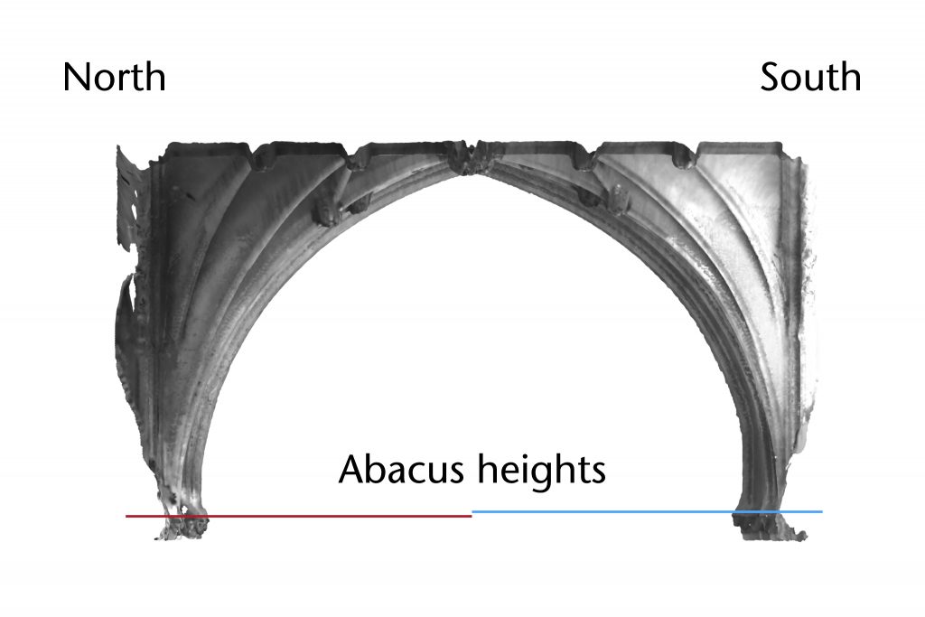
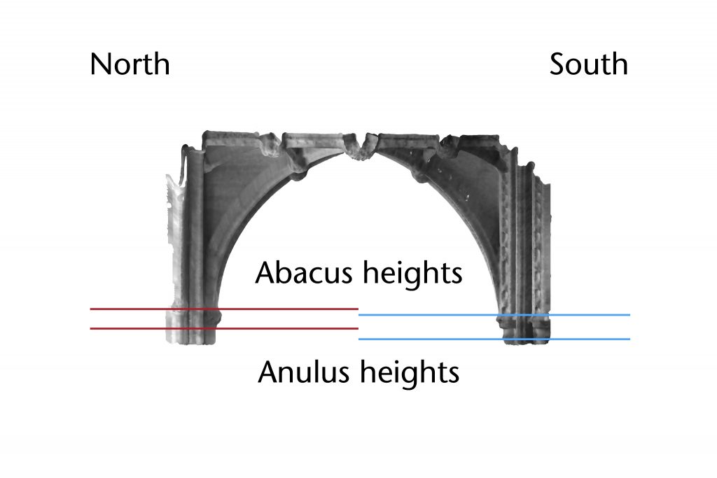
The difference between multiple phases would have presented a number of challenges to the vault’s designers. The apex height of the vault (average 5.95m) was set by the great eastern arch of Northwold’s presbytery, which predated the design of Hotham’s choir by almost a century. Whilst the apex remained relatively stable throughout the bays of the choir, being used for both the longitudinal and horizontal ridges, the height of the impost level is more variable. The height of the abacus on the earlier works of the south wall are roughly 0.20m lower than those on the north side, bringing down the impost level of all the ribs springing from the northern tas-de-charges. This was a surprisingly common feature of medieval vault design and was particularly widespread during the eleventh and twelfth centuries. The same phenomenon could be seen in the West Range at Norton Priory or the crypt and ambulatory at Gloucester Cathedral, for example, and later designers often had to contend with the same problem when revaulting older spaces as in the nave aisle at Tewkesbury.
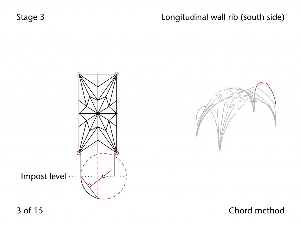
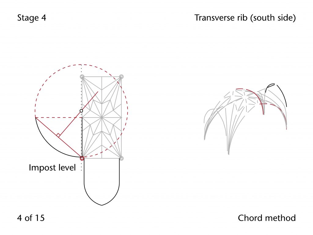
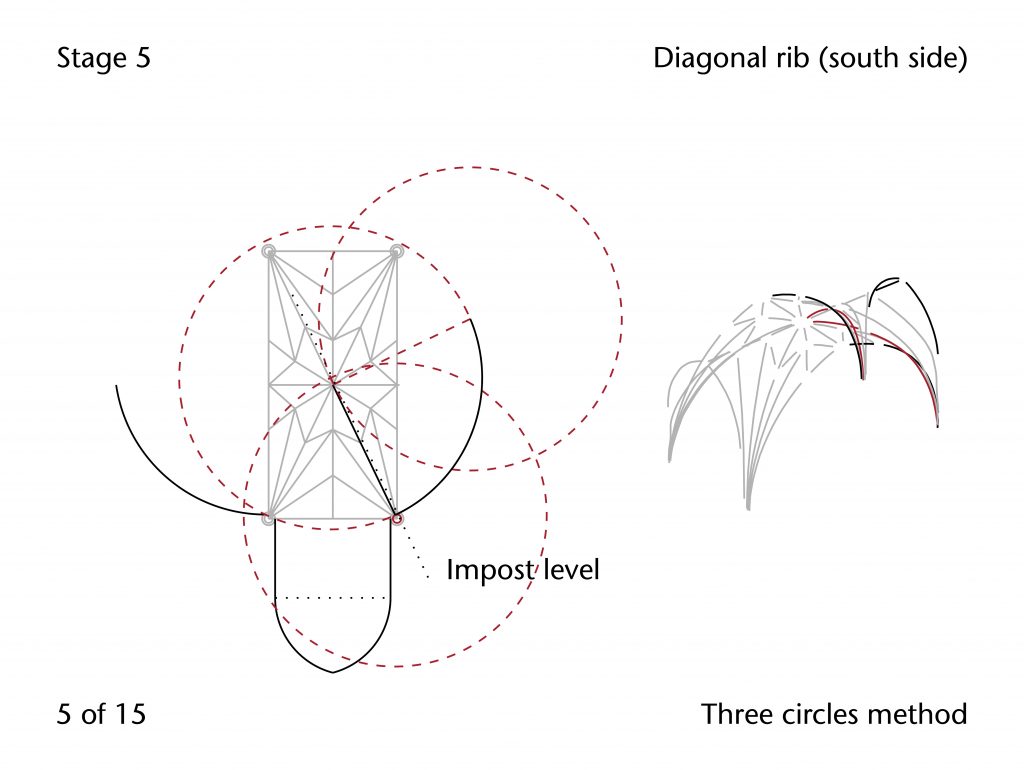
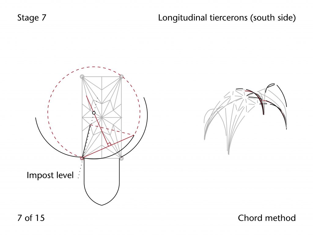
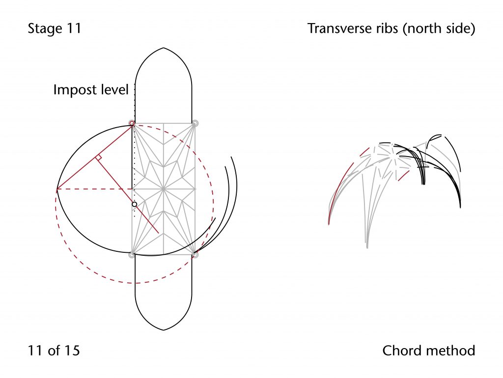
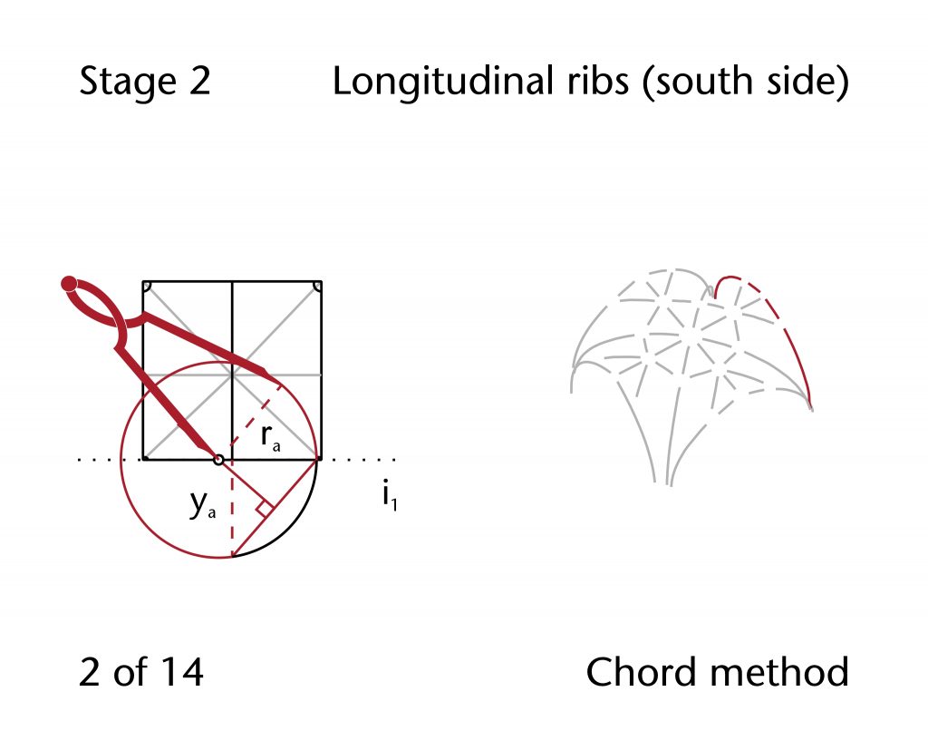
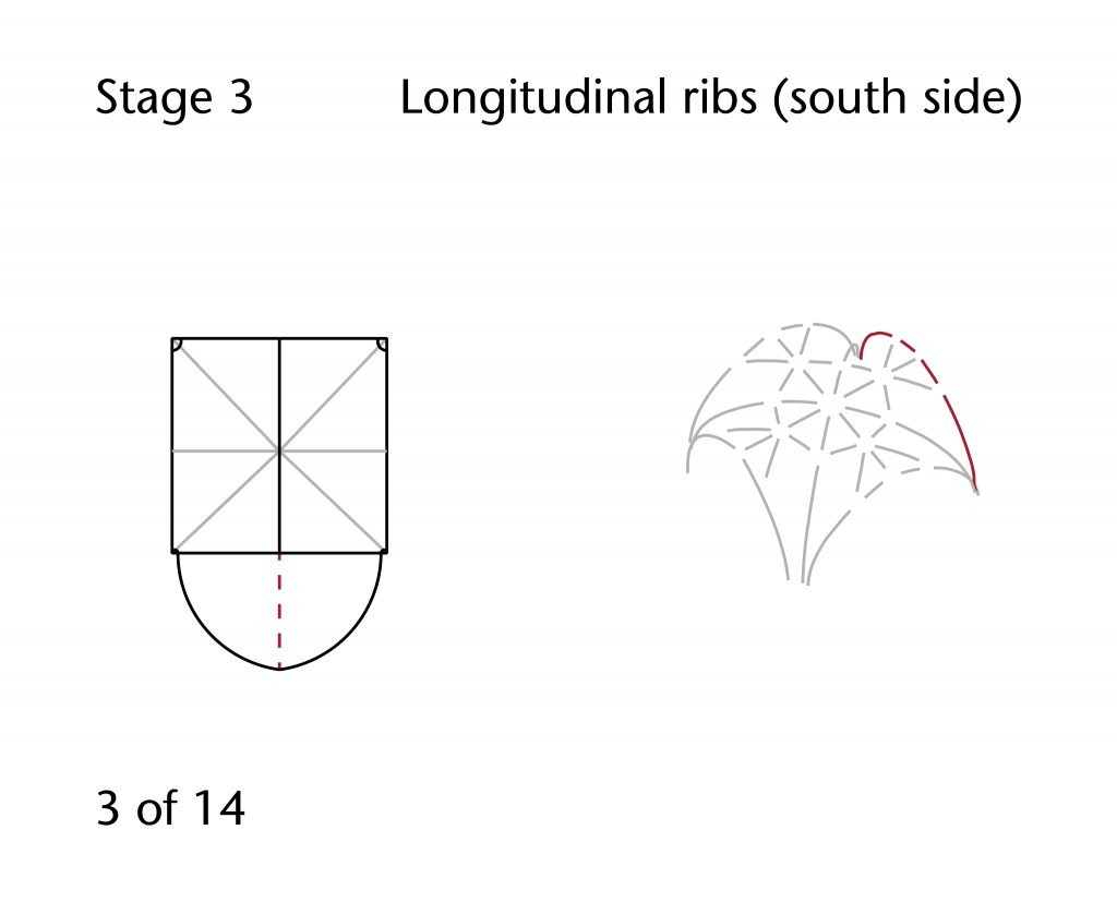
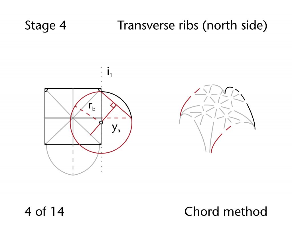
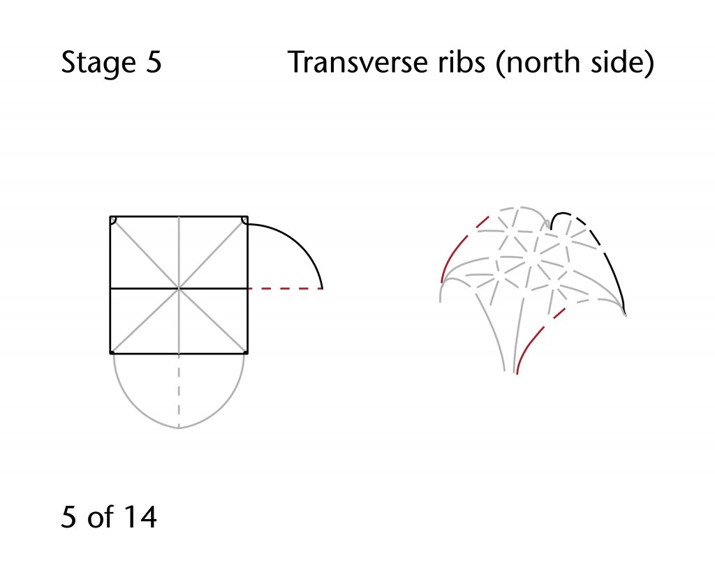
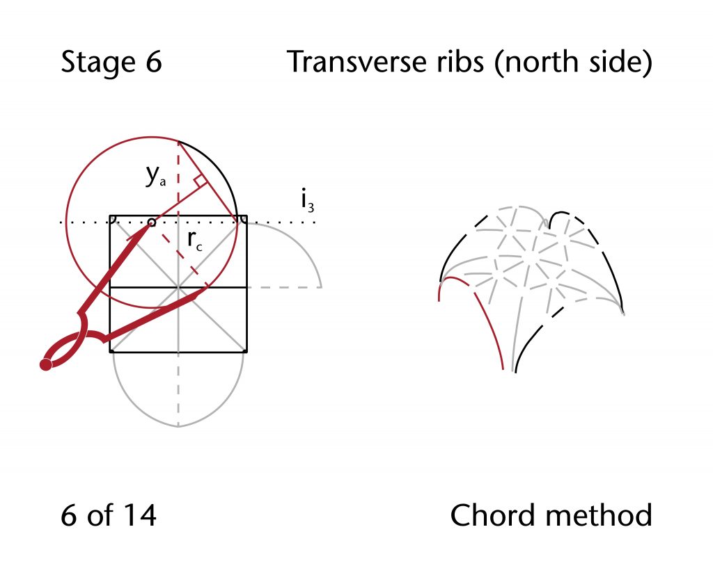
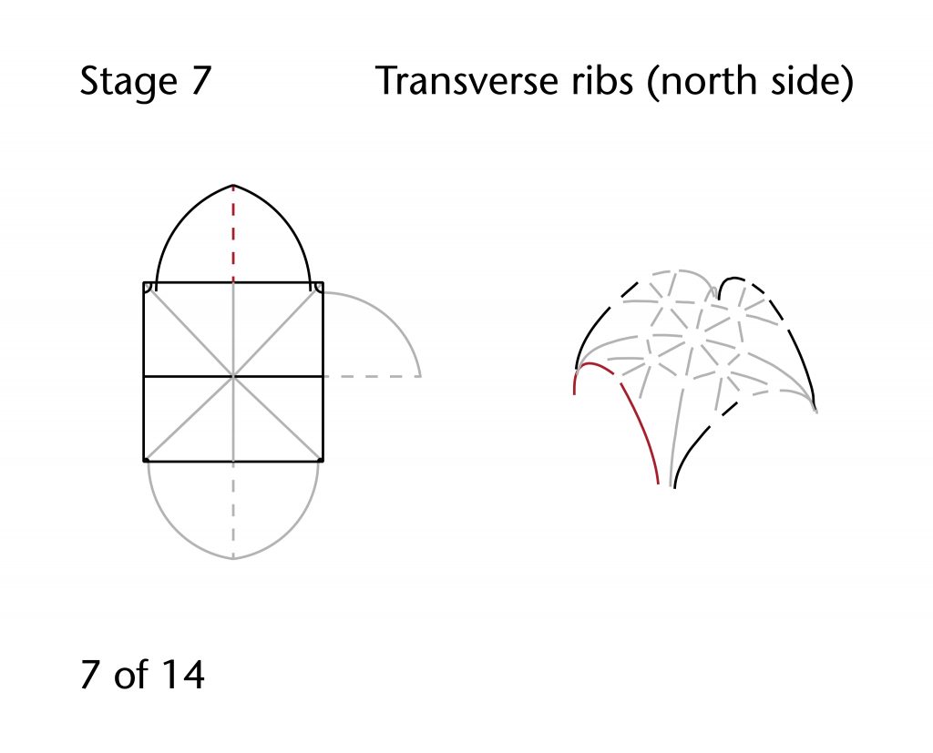
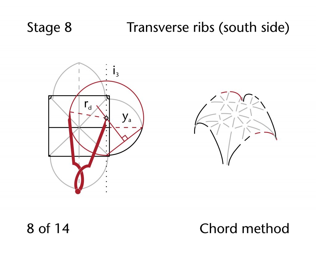
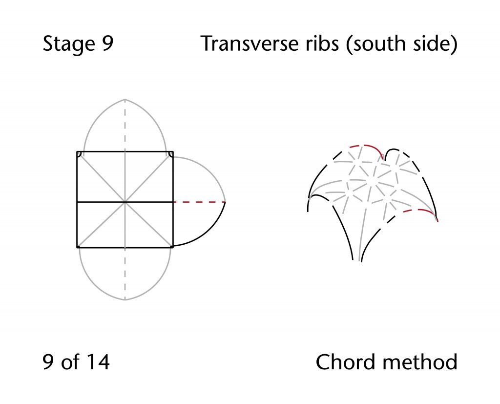
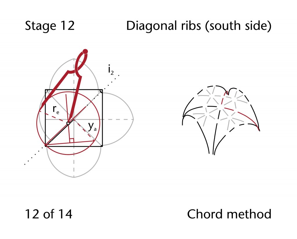
The solution which seems to have been adopted at Ely was to embrace the multiple impost levels, resulting in a slight difference in design process between the ribs on either side. On the south side the process was relatively straightforward. With the apex height and span for the ridge, diagonal, transverse and longitudinal ribs were defined in advance, it was likely that the starting rib would be designed using the chord method. First the springing points would be set out in plan, though the difference in abacus height would need to be incorporated going forwards. Following the design of the clerestorey, the longitudinal wall ribs are stilted, giving a far higher effective impost level to the rib. Their curvature seems to have been defined using the chord method. The same approach was probably also used for the transverse rib, with the centre being located at the level of the southern abaci. The radius of this arc may then have been transferred to the diagonal ribs using the three circles method.
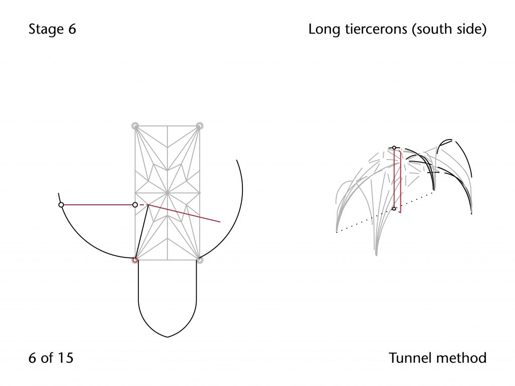
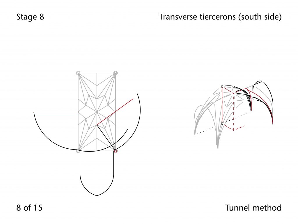
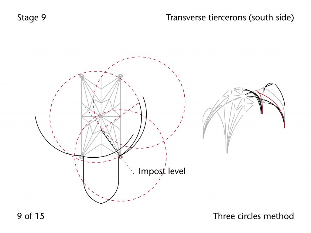
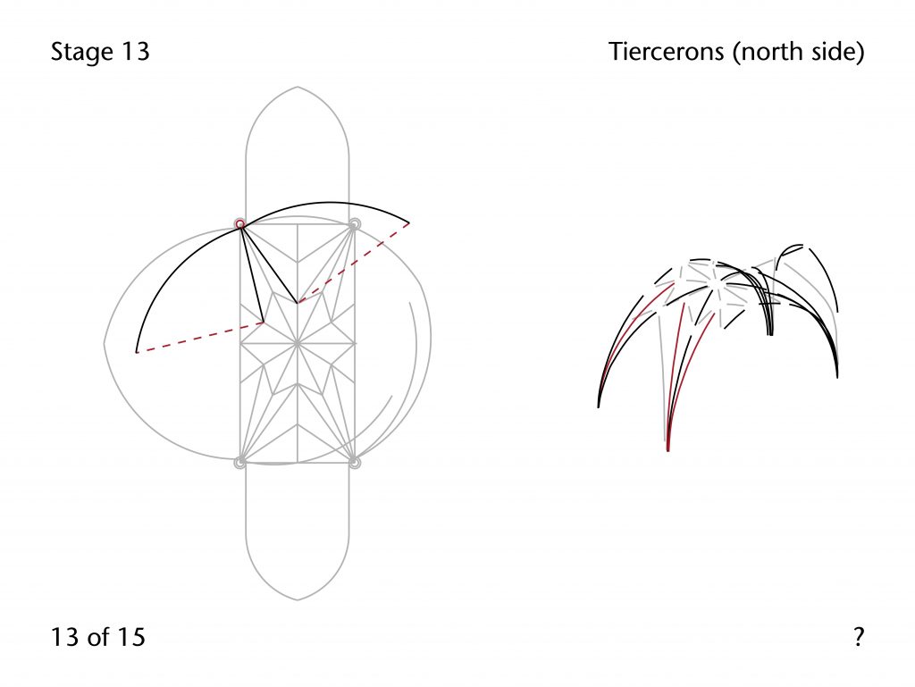
In addition, the tunnel method would be used to generate the apex height required for the longitudinal tiercerons, measuring it from the equivalent position along the span of the transverse rib. The chord method could then be used to set out the curvature of the longitudinal tiercerons, which could then be transferred to transverse tiercerons using the three circles method.
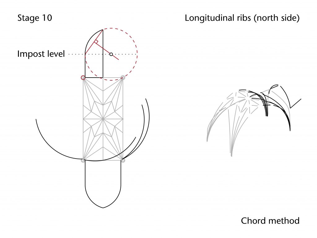
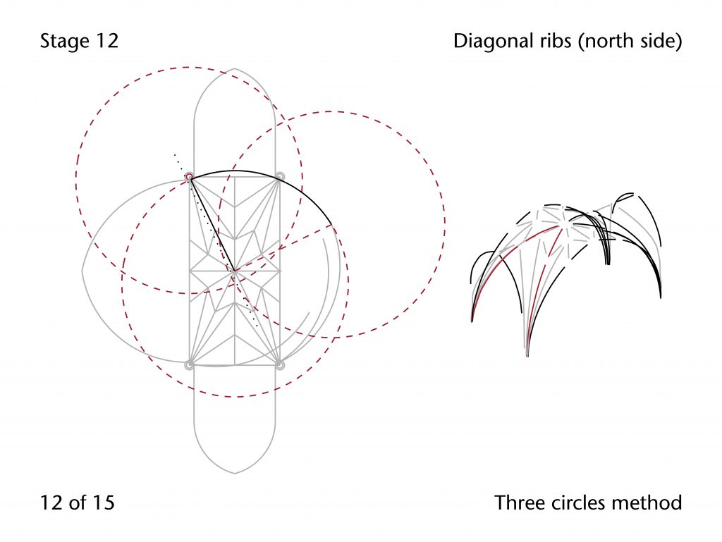
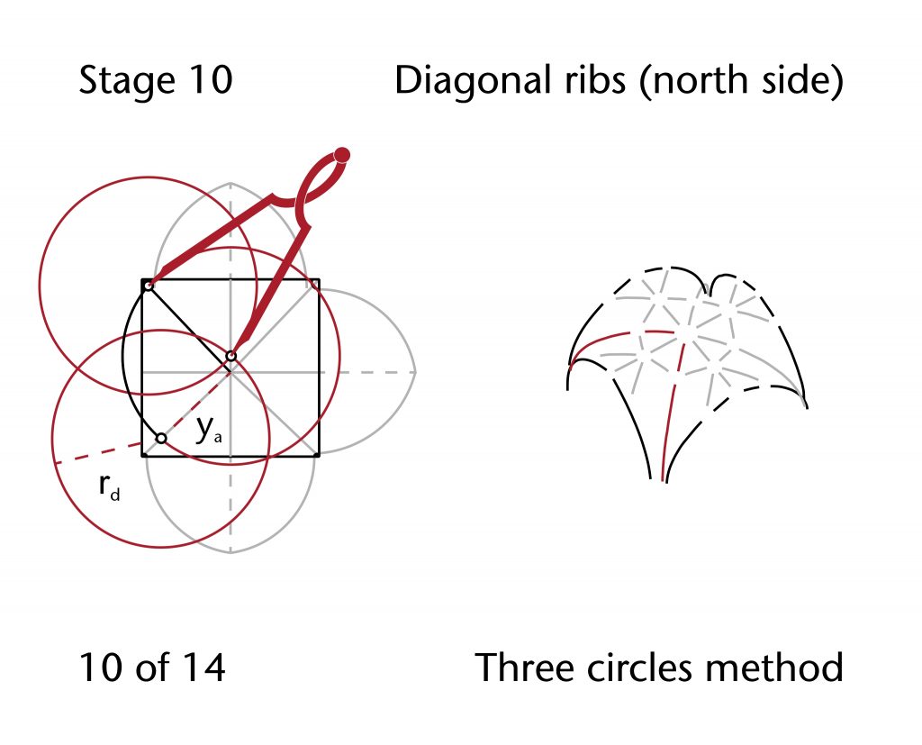
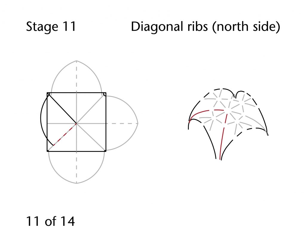
The design process for the ribs on north side, however, is far more difficult to unravel. The centres of the rib arcs are far lower than those on the south side and the radii used are entirely different, suggesting that there was a significant change in geometry between the two sides. The transverse and longitudinal arches could have been set out using the chord method. In both cases the height of the centres was lower than on the north side, the transverse ribs being -0.22m below the average impost level. This suggests that the impost may have been set around 0.10m lower than the level of the abacus when designing the vault, a phenomenon which has been observed in other sites such as Exeter. Whilst the centre for the diagonal ribs is on average significantly below impost level (-0.28m), the mean radius (6.43m) is near identical to that of the transverse rib (6.42m). This suggests that the diagonal ribs were set out using the three circles method, with the curvature being transferred directly from the transverse arch.
The radii and impost levels for the transverse and longitudinal tiercerons, by contrast, are far more difficult to explain. The positions of the centre below the impost line are approximately the same (-0.25m for the longitudinal tiercerons, -0.26m for the transverse tiercerons), but the radii are dramatically different (7.07m and 6.78m respectively). Consequently, it is difficult at the present stage to propose any meaningful model for their geometrical construction. Similar issues apply to the remaining tiercerons and liernes, where the shorter spans of the ribs make it hard to extract useful data through tracing best fit lines. It is possible that further research will reveal a more conclusive explanation for the vault’s irregular form, either through additional analysis of the scanned data or careful study of the building’s stonework.
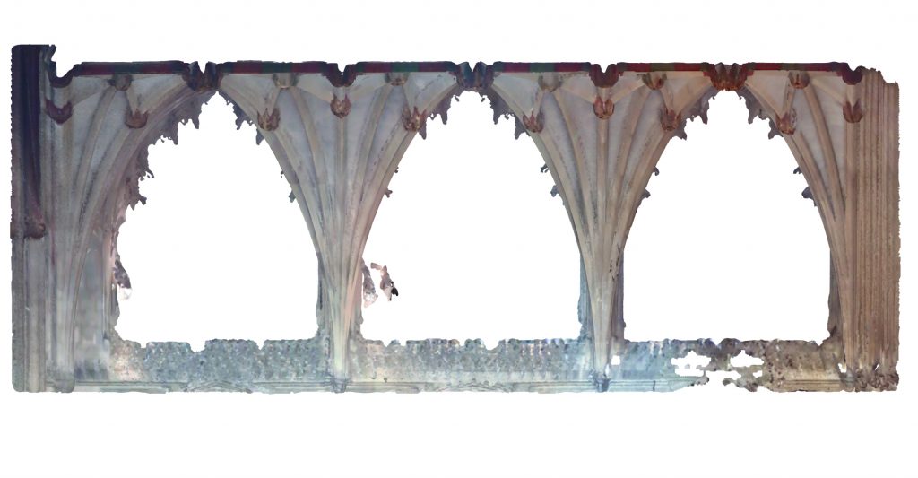
North Aisle Vault
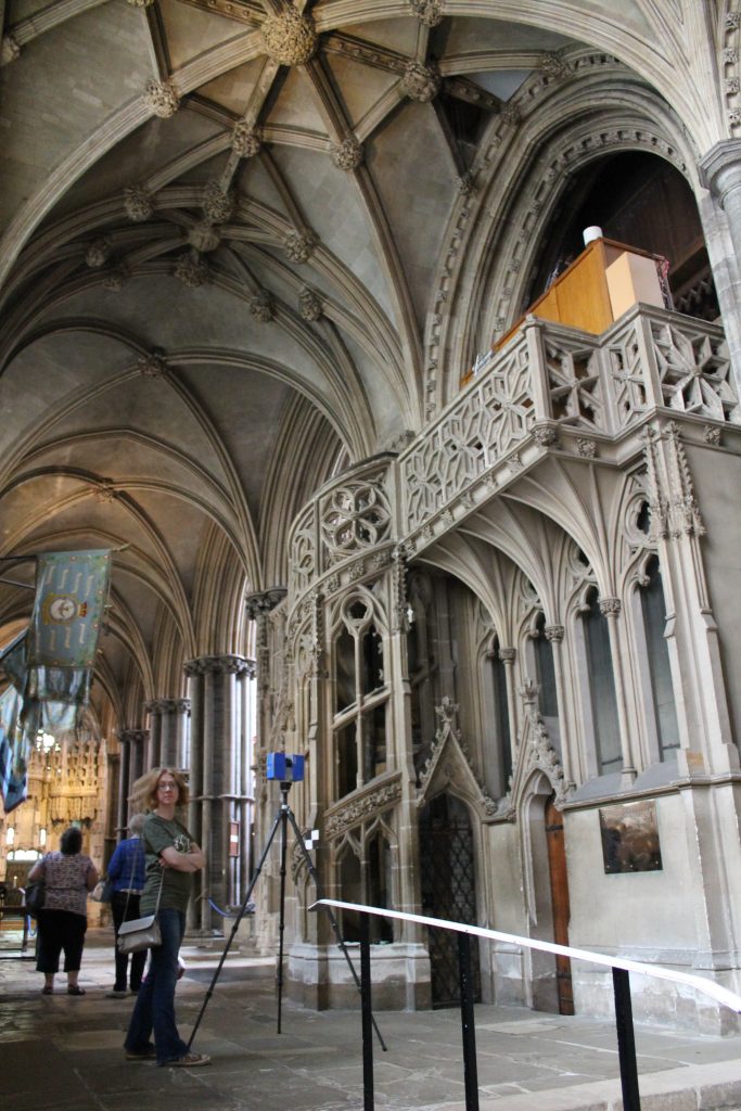
Similar problems of interpretation are presented by the vault in the north choir aisle. Not only are the bay lengths in the north aisle are just as variable as those in the central vessel above, but there is also a difference in impost level between the north and south sides. Consequently, it is difficult to provide a definitive design process for the vaulting in the north choir aisle. However, the traced data does allow us to propose a tentative hypothesis which can be tested by comparison to our laser scans.
Vault Plan
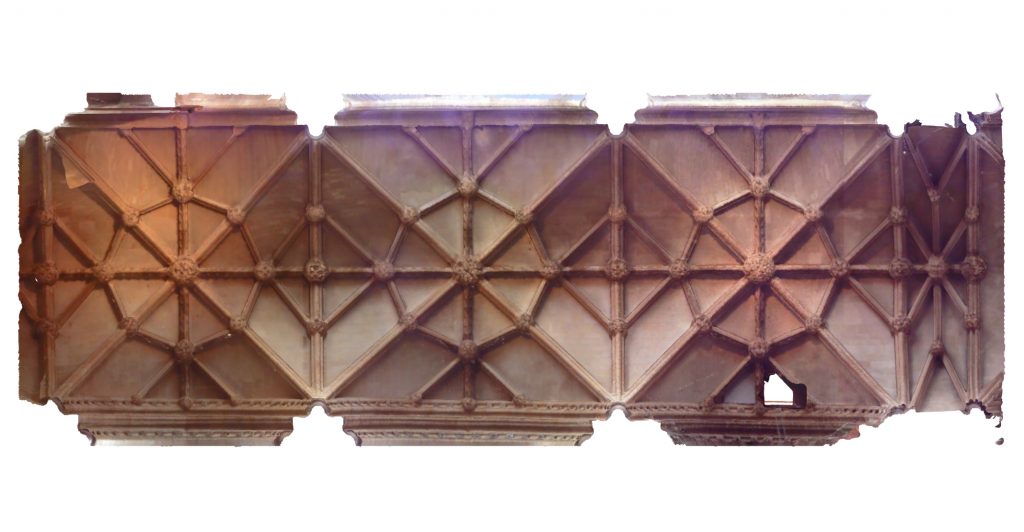
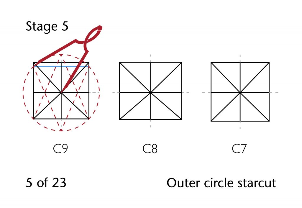
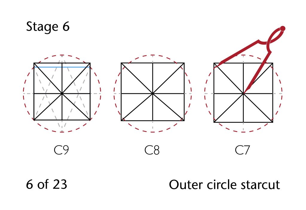
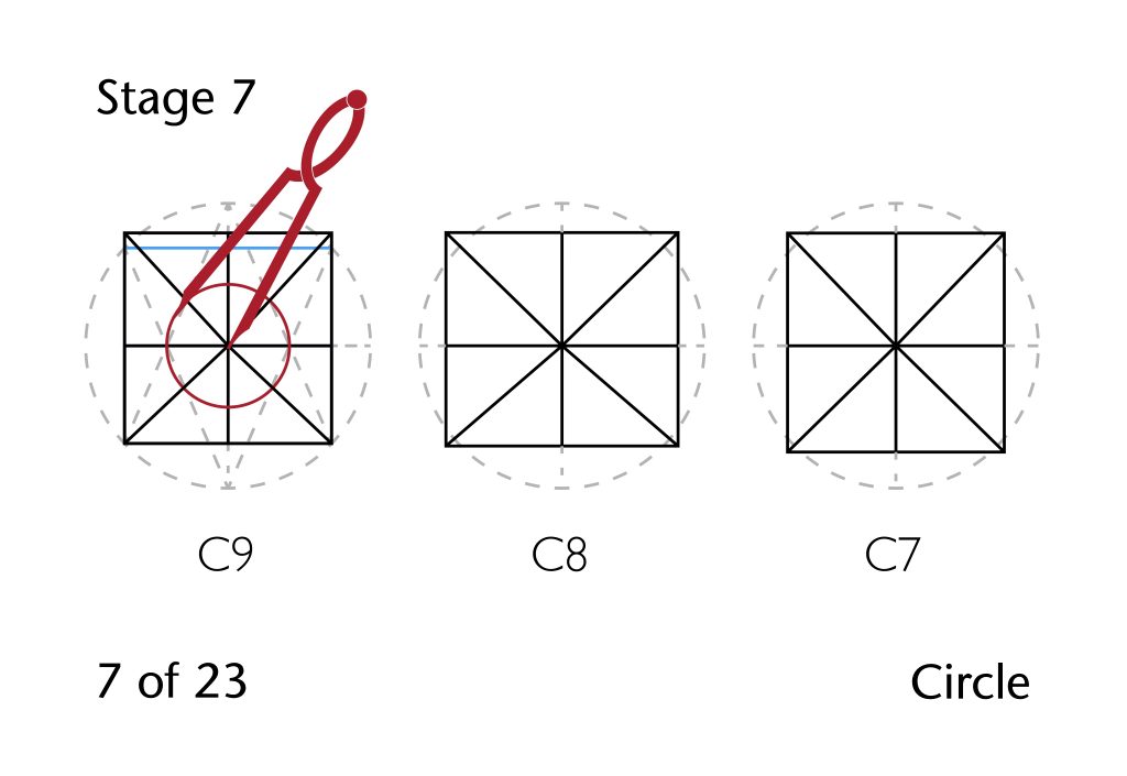
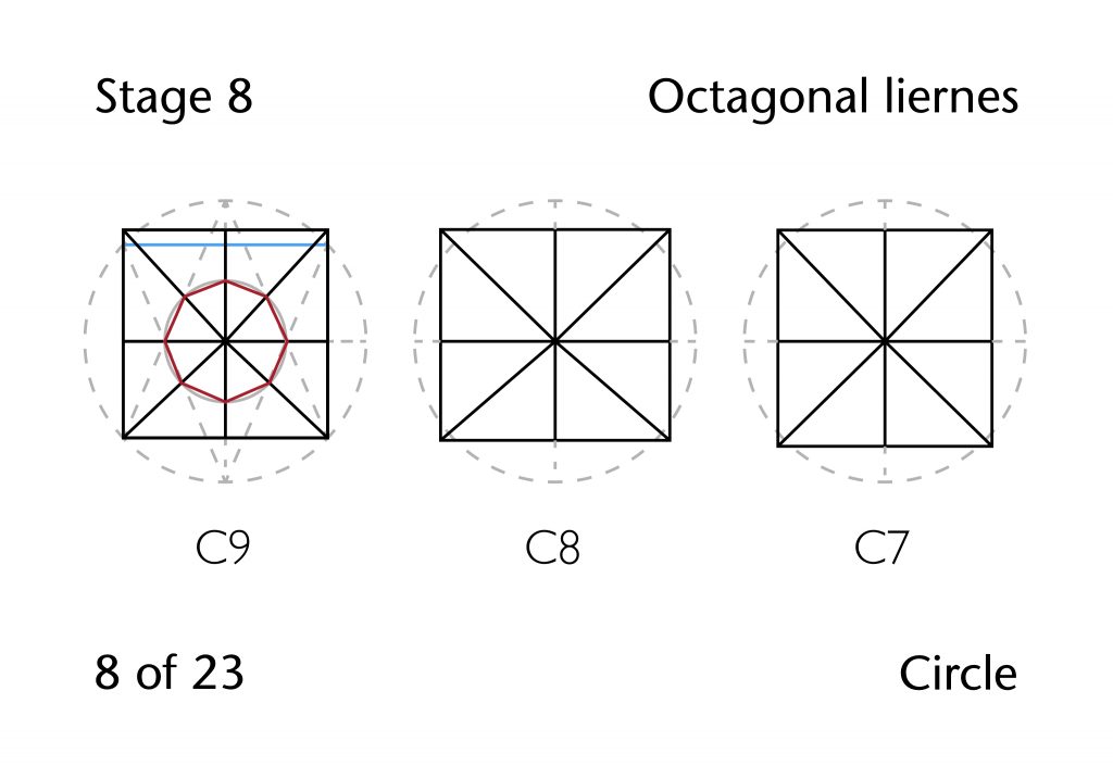
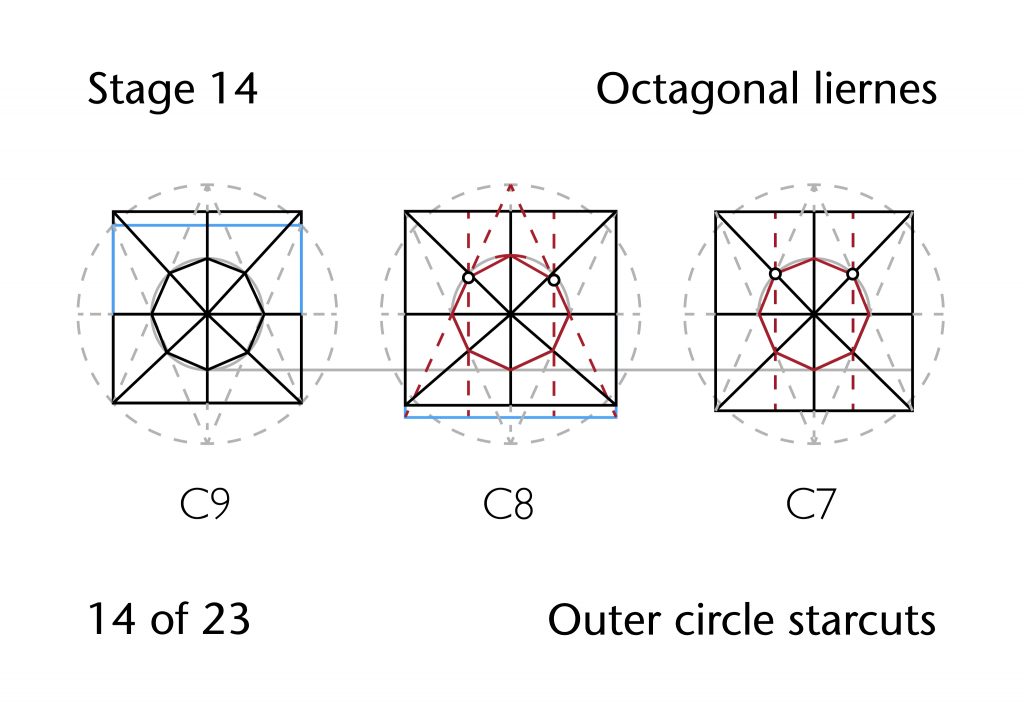
On first inspection, the design of the vault plan appears to be relatively straightforward. Whereas the high vault of Hotham’s choir made use of an inner circle starcut, the defining figure for the aisle vault was an outer circle starcut. Once the ridge ribs and diagonals had been drawn in, the outer circle starcut was used to establish an inner octagon of liernes, providing the points necessary for defining the remaining outer liernes.
Whilst such a setting out process may have been the original intention of the vault’s designers, they would have encountered the same problems in transferring their design between bays as they would in the main vessel of the choir. The dimensions of the north choir aisle vaults vary considerably from bay to bay. Not only are all three bays different lengths, but also the wall rib on the south side is slightly slanted throughout the length of the aisle, resulting in a gradual expansion in bay width from west to east.
The decision to use an outer circle starcut would have meant that any change in length or width would have a direct effect on the radius of the starting figure. If the same method was used throughout the aisle, then the entire proportional structure of the vault would be different in every bay. Consequently, if the designers intended to maintain a similar form throughout the vaults of the north choir aisle, they would need adopt an alternative, bay-by-bay approach to setting out their design.
It is therefore unsurprising that when our initial hypothesis was superimposed on the traced data, there was a noticeable disparity between the predicted model and the recorded intrados lines. The most striking difference is that the longitudinal ridge rib was not positioned along the midline of the bay, but was consistently offset slightly to the south. Repositioning the starcut to this location did help to bring the hypothesis closer to the recorded data, but there were still noticeable inconsistencies between the two results, especially in the central bay.
In order to investigate the design process further, we extended the lines of the traced data using 2D CAD software. By marking the actual points of intersection for the lines of each of the ribs, we were able to identify several patterns within their geometry. Whereas the positions of the east and west points of the starcut vary considerably from bay to bay, the north and south points can consistently be placed on the same circle within all three bays. The radius of this circle appears to intersect approximately with the corners of the westernmost bay (C9), with the same circle being reused for the remaining two bays (C8 and C7). However, the lines of the starcut do not converge on consistent points from bay to bay. In bay C7 the corners of the bay plan appear to have been used, but in bay C8 the southern half of the starcut is based around points located to the south of the actual bay corners. The location of these bays appears to be given by expanding the width of the southern side of the bay to the same as that of the north, producing a more uniform structure within which the starcut could be set out. Something similar seems to have taken place in bay C9, where the northern side of the starcut is also based on points located to the south of the actual bay corners, their location defined by reducing the width of the bay plan’s north side to the same as that of the south.
It is therefore evident not only that the geometry of each bay was set out individually, but also that it was mutually interdependent. Consequently, the design of each bay of vaulting was not worked out independently, but simultaneously. An outer circle starcut in bay C9 provided the defining figure for the entire run of vaulting, which was subsequently modified for the remaining two bays. The radius was provided by the distance from centre to corner in the southern half of the bay plan, providing a circle which could then be transferred to bays C8 and C7. Once the octagonal liernes had been defined, perpendicular lines could be used to transfer the positions of some of them from one bay to another, just as in the vault of the main vessel above. The remaining liernes would then be set out using a combination of perpendiculars, intersecting lines, the starcut and further translations of position from bay to bay.
Rib Curvatures
Yet further complexity was introduced in converting the two-dimensional plan into a three-dimensional structure. The apex height of the vault (ya) appears to have been given by the height of the arcade arches to the south, and is slightly higher than the longitudinal ridge of Northwold’s presbytery aisle to the east. This appears to have been used relatively consistently as the apex height for all the ribs along the longitudinal and transverse ridge ribs, with the notable exception of the wall ribs on the north side in bay C8. As in the high vault above, there is a significant difference in height between the abacus of the capitals on the north and south walls, resulting in a higher set of springing points on the north side. Whatever the design process of the vault was, it would therefore have to accommodate this change in height, especially when considering the level of the impost.
The approach which the designers seem to have used involved varying the impost level from rib to rib. The majority of the ribs in the vault were probably set out using the chord method, as the apex height was defined in advance and their centres were positioned at one of three defined impost levels. The first of these was located at the level of the abacus on the north side (i1), the second at the top of the abacus on the south side (i2) and the third at the level of the lower anulus on the south side (i3). The only exception to this was the diagonal ribs on the north side, which appear to have been laid out by using the three circles method to transfer the radius from the transverse ribs on the south side (rd).
The result is a highly flexible vault design which can readily be adapted to the changing dimensions within each bay. Both vault plans and rib curvatures were worked out on a bay by bay basis, the process requiring all three vaults to be designed at the same time. By working back and forth from vault to vault, the designers were able to produce an integrated run of vaulting which nevertheless was tailored to the particular demands of each individual bay.
Further Reading
- Buchanan, A., Hillson, J. and Webb, N. (2021) Digital Analysis of Vaults in English Medieval Architecture. New York and London: Routledge.

2 Comments
[…] out more about the history of the site Find out more about out digital surveying methods Find out more about vault design in Hotham’s Choir at Ely Find out more about vault design in Ely Lady […]
[…] Find out more about vault design in Hotham’s Choir […]