Designing a medieval vault was not simply a matter of applying a set of rote-learned geometrical procedures. Instead, the vault’s form was the product of a series of decisions, often reflecting a wide variety of practical concerns. Many of these choices would have been prompted by the existing fabric of the building below, but others would have been freer and more open-ended. Each decision in turn would both expand and limit the range of possibilities available to the designer, establishing a framework within which the three-dimensional form of the vault could be devised. Whilst we cannot be certain exactly what took place in the design process for each individual vault, it is possible to identify some of the issues which medieval designers would have faced, and consequently what kinds of questions they might have addressed.
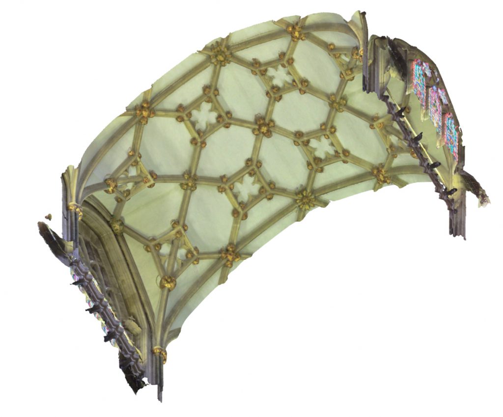
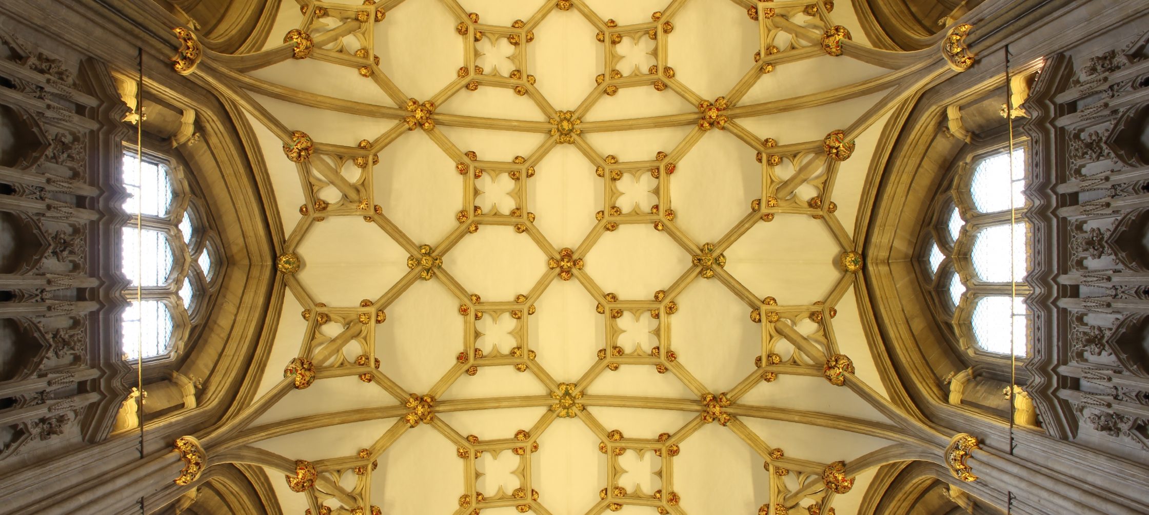
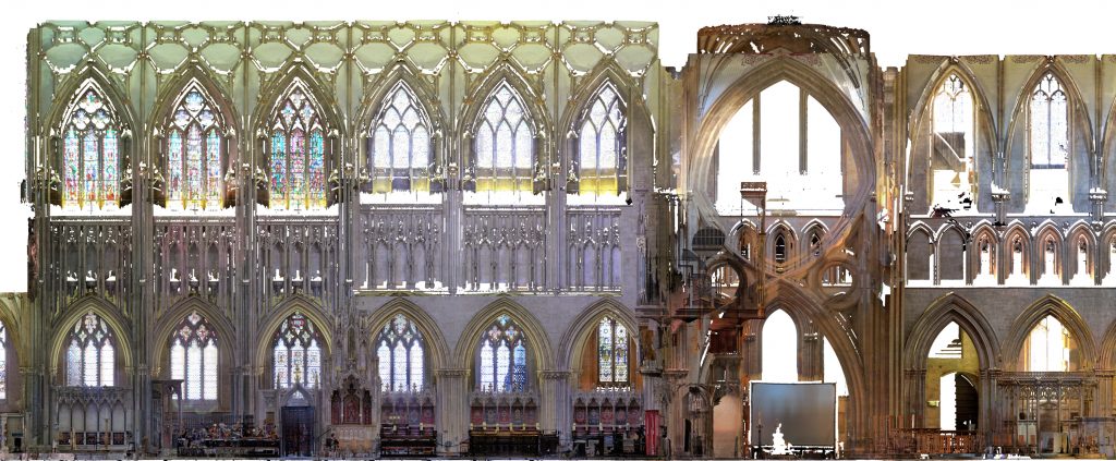
The easiest way to explore such questions is to focus on a particular example by following through the design process for one particular site. The choir vault at Wells Cathedral was probably constructed around the 1340s and is widely considered to be one of the pioneering examples of net vaulting in medieval England. The ribs form a criss-cross pattern divided by distinctive squares, their network of lines seemingly draped over the surface of a longitudinal tunnel of uniform curvature. The plan, structure and individual curvatures of these ribs were devised in a complex, iterative process, consisting of a series of design choices made through an extended process of discussion and formal experimentation on the part of its designers. Whilst these decisions can be discussed in a logical sequence, they cannot easily be separated into distinct phases. Almost of the design decisions made in medieval vaulting were mutually contingent, requiring the designers to work backwards and forwards between multiple phases in order to realise the structure’s full three-dimensional form.
Bay plan
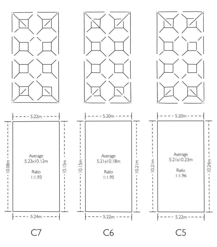
The first step in any design process was to decide on the shape, dimensions and/or proportions of the individual vault bays. The details would usually have been set out during a previous stage of the building’s construction, often at the level of the foundations. At Wells Cathedral, the choir bays are rectangular, with an average length of 10.17m and an average breadth of 5.22m. This gives an average breadth to length ratio of 1.948:1. Consequently, it is possible that the bays were originally intended to be set out using a 2:1 modular proportional system. Though the boundaries of these bays were set out by the existing fabric of the choir below, this does not necessarily mean that the exact form of the vault had already been designed at this early stage. Instead, it would have been more conventional to wait until later before finalising the details of the vault’s design, especially when considering the pattern of its plan or the curvatures of the ribs.
Vault plan
With the bay plan set in place, the designers next needed decide what pattern of ribs they were going to impose on the vault’s surface. The complexity of this pattern would depend on a range of different factors which varied from site to site. First and foremost would be the skill and experience of the designers themselves, as well as the masons under them. Expense could be a limiting factor for some architectural projects, but in other cases it may have been desirable. Practicality was another concern, as not all designs were possible within the structural limitations of the building or the constructional techniques available to the masons. Decoration may also have been considered, in particular the number of bosses required for a particular programme of figurative sculptures. However, such decorative programmes were more often adapted to fit the pattern of the vault than the other way round. Amongst the most significant question faced by medieval designers was one of decorum. Not all designs were fitting for all spaces, as the level of opulence desirable for a choir may not have been appropriate for a cellar or refectory.
The choir vault at Wells would have presented a number of difficult problems for its designers. Whilst it needed a level of decoration appropriate to the function of the choir below, it also appears to have been important not to overpower the simpler vaults found in the adjoining nave and transept. Furthermore, the architecture of the walls below was very rectilinear in form, its surface dominated by a set of niches enclosed within rectangular compartments.
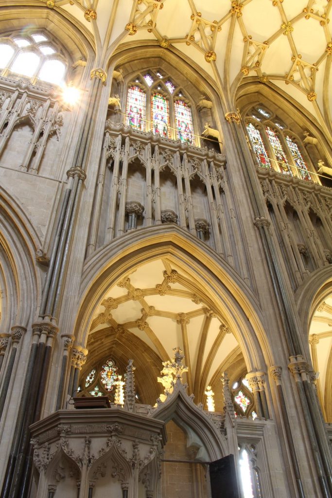
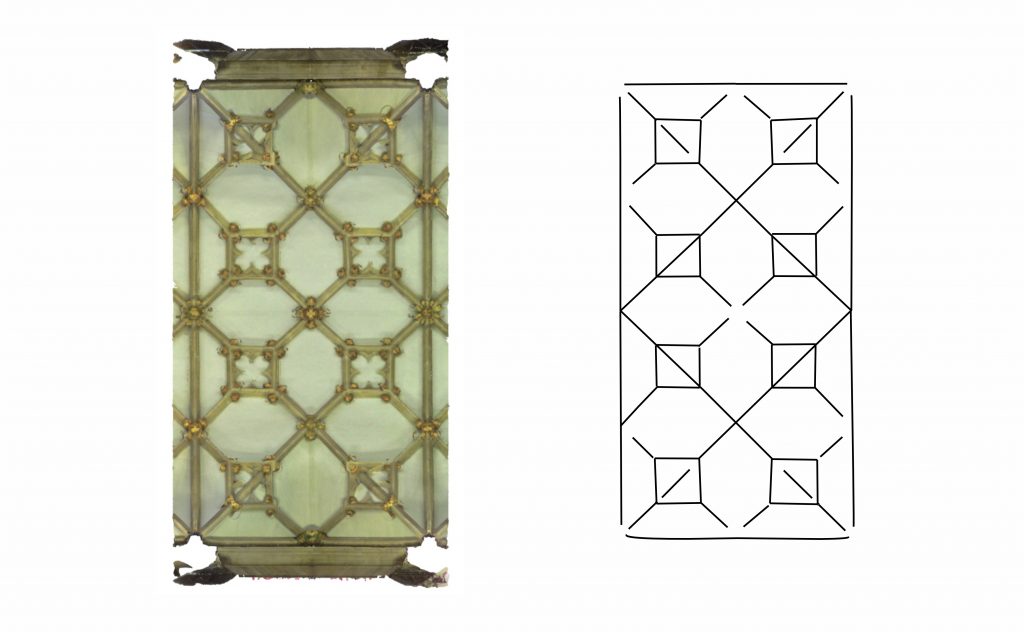
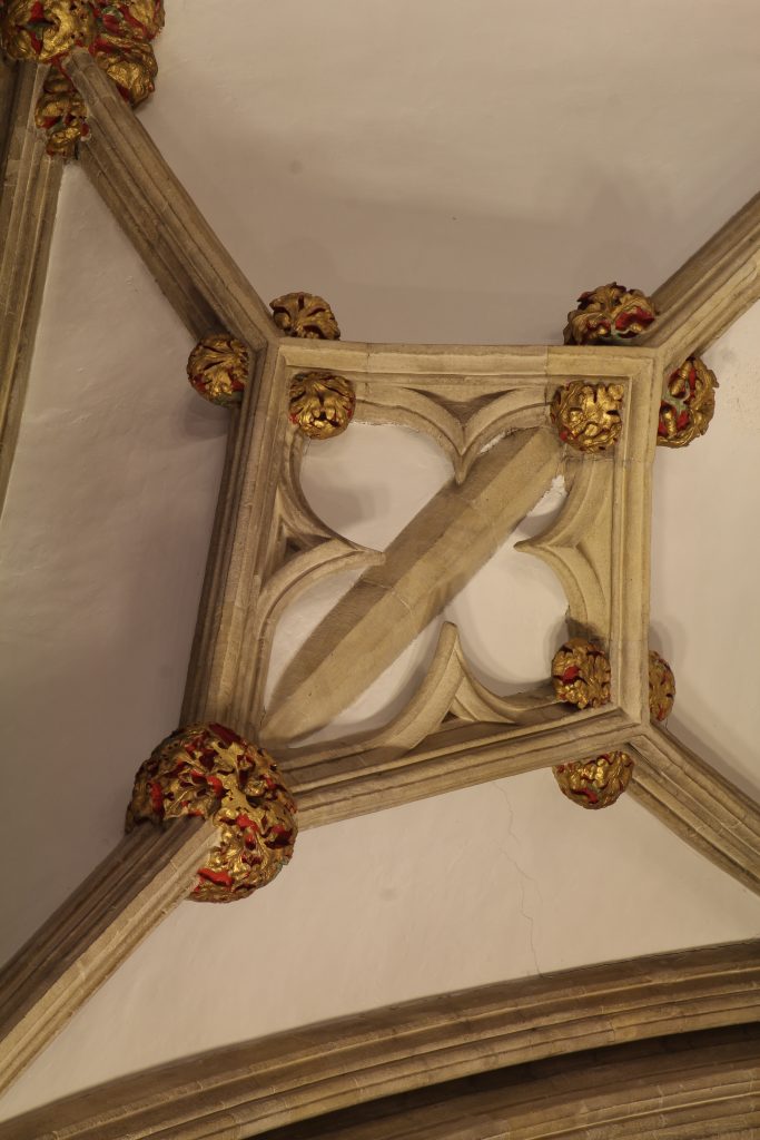
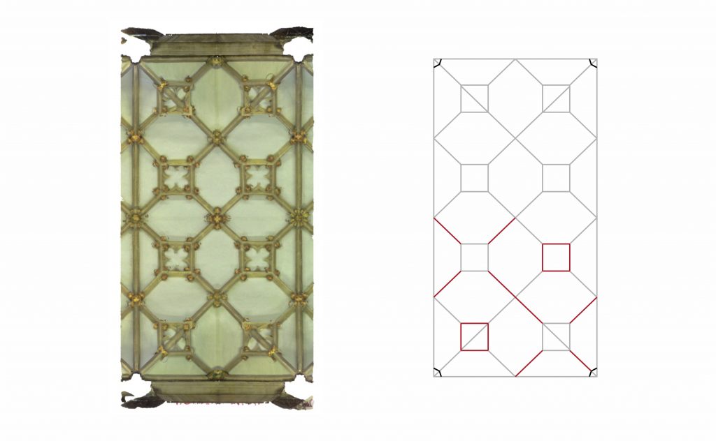
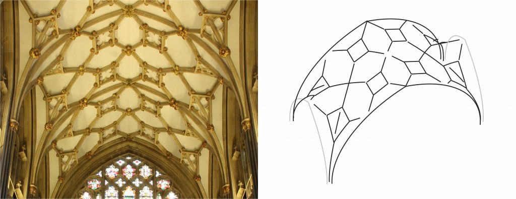
Both the contrast between simplicity and decorative complexity and the linearity of the surrounding architecture appear to have been reflected directly in the vault’s form. The key concept was to articulate the vault plan using a pattern of diagonal crosses, resulting in a compartmentalised structure. At the centre of each compartment is a square arrangement of liernes, dividing up the diagonals and reinforcing the rectilinear structure of the bay. Whereas the majority of the lines in the vault are smooth, clear and simple, the squares provide focal points for decorative complexity, each one filled with tracery and supporting multiple layers of ribs. When viewed from an angle, they take on distorted lozenge shapes, mediating between the rectilinear lines of the architecture below and the smooth curvatures of the vault above.
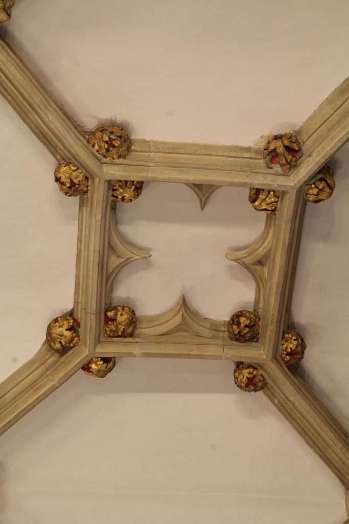
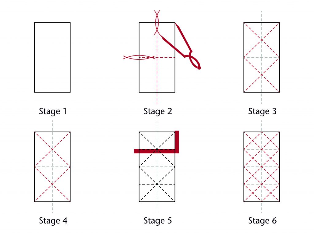
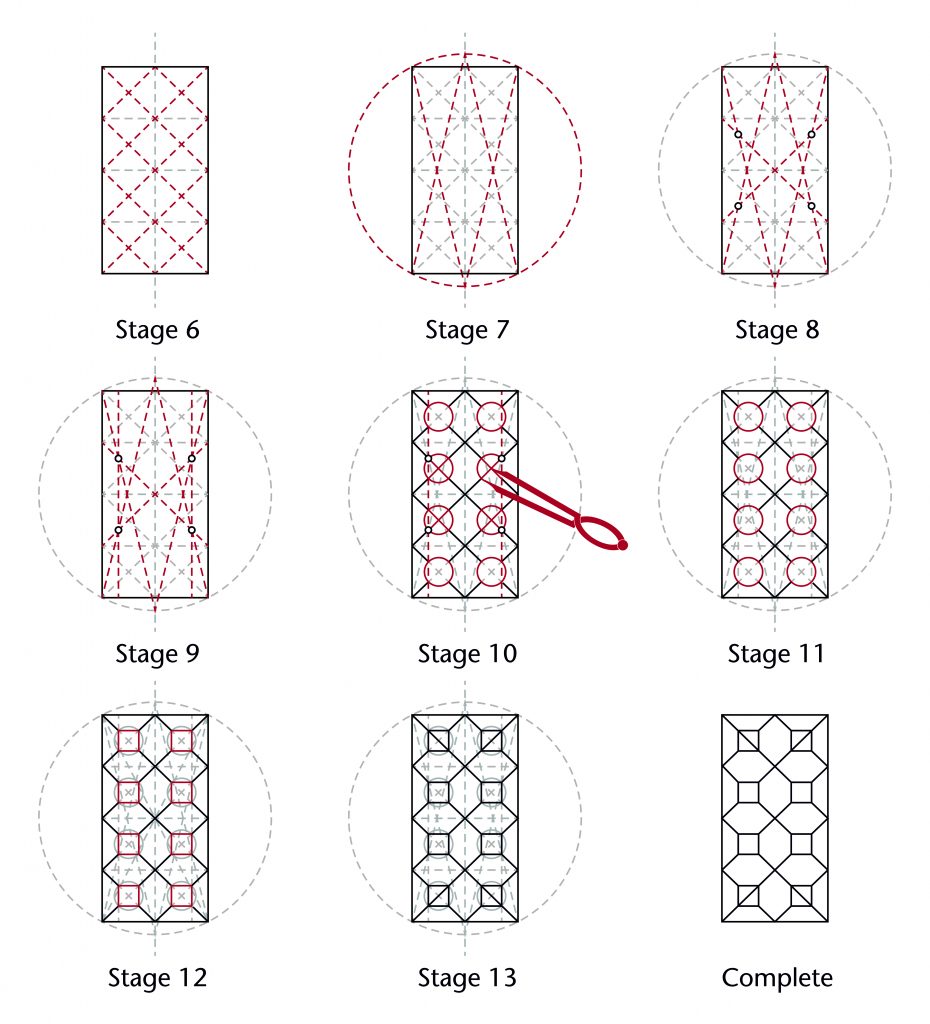
Once the initial concept for the vault plan had been worked out, the principal difficulty would have been how to articulate the idea geometrically. Rather than using a starcut as the starting figure, the designers at Wells instead appear to have focused on a grid of crosses. The vault was divided into two approximately square sections along its longitudinal axis, and the diagonals of each were drawn in. These could then be used to divide the vault into quarters, providing the framework for drawing another set of diagonal crosses and effectively subdividing the plan into eight approximately square sections:
The next problem would have been how to define the squares at the centre of each compartments. One of the simplest solutions would have been to use a regular starcut to divide the longitudinal side of the vault into sixths, using the points of intersection between the starcut and the diagonal cross grid to set out the boundaries of the squares. However, when this approach was compared to the traced data, the resulting squares were all significantly smaller than those in the actual vault:
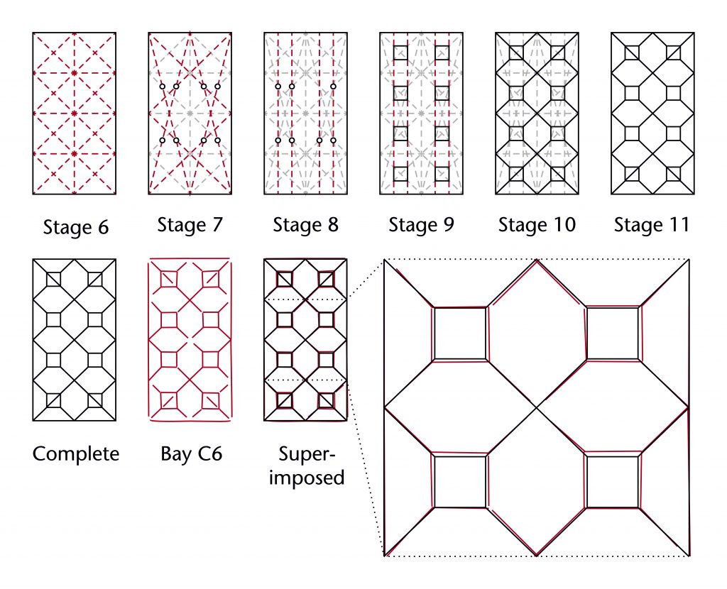
If the designer wished to enlarge or reduce the size of the squares, there would have been several options using the starcut itself. There were several additional points of intersection between the starcut and the diagonal cross grid which could have been used to define the sides of the squares. Alternatively, the designer could ignore the diagonal cross grid entirely, using the starcut to divide the vault plan into a different set of fractions.
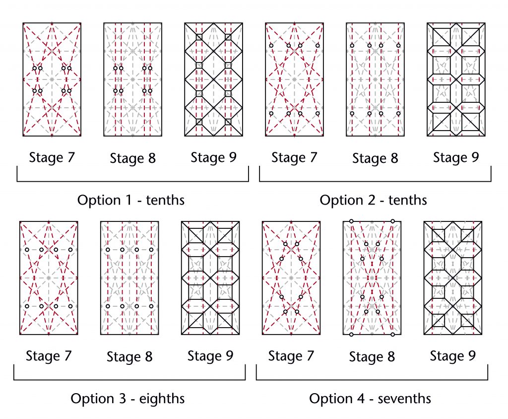
None of these options, however, appear to have been employed by the designers of Wells Cathedral choir. Instead, they appear to have moderated the size of the squares by using a partial outer circle starcut. Due to the specific proportions of the bay, this resulted in a slight expansion in the squares compared to the regular starcut. Once their specific geometries had been established, the rest of the ribs could be drawn in, bringing the vault plan to completion:
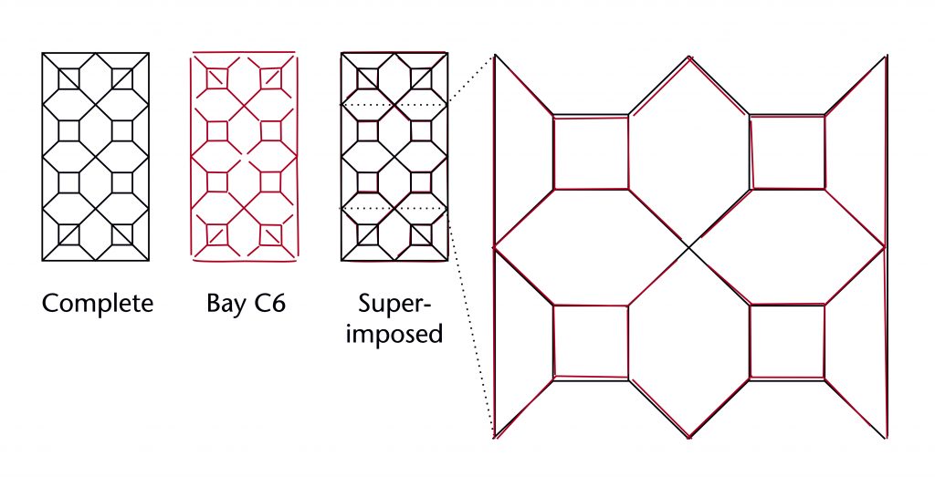
The resulting vault plan is far closer to the traced ribs than can be achieved using a conventional starcut. Similar uses of the outer circle starcut have been found in several of our sites, suggesting that it was a common method of modifying the proportions of the rib pattern.
Whilst it is impossible to know exactly how the vault plan of the choir at Wells was designed, the above examples show how the possibilities which the starcut and other geometrical figures could provide. The geometrical techniques used by masons were not just a rigid method of imposing proportions on the vault plan, but instead a speculative tool which encouraged a flexible, open-ended and often playful attitude towards architectural composition. Designers could use the patterns formed by their construction figures to test a wide variety of alternatives extremely quickly, trying out different lines or geometrical constructions to see what worked and what did not. Through this iterative process the general idea for vault’s plan could be gradually refined, with variations in geometry allowing for both subtle and conspicuous changes to its individual forms.
Defining parameters
Once the vault plan had been decided, it would then be necessary to work out how to translate into three-dimensional form. Vault design was more often about working within existing parameters than pure creative freedom, as many aspects of its design would have been fixed by the architecture of the walls below. However, such parameters were not in themselves capable of defining the curvatures of the ribs, as there were always several different options for setting out their forms.
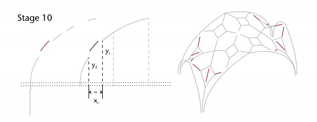
Span
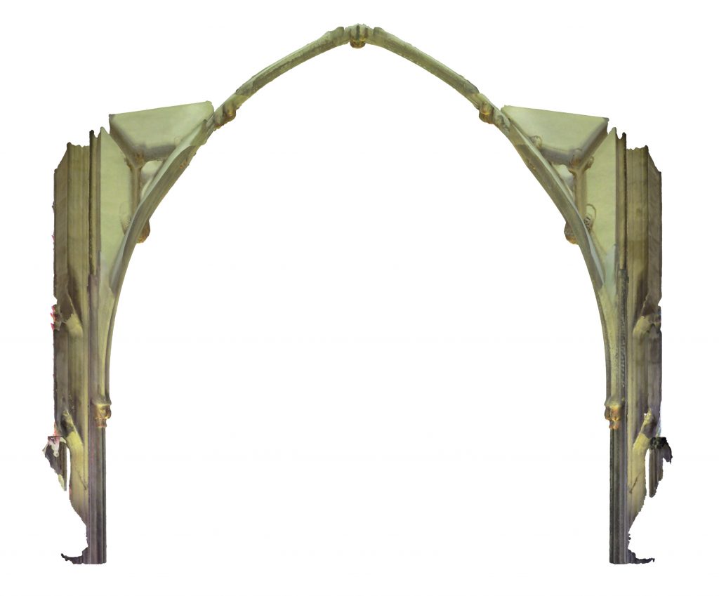
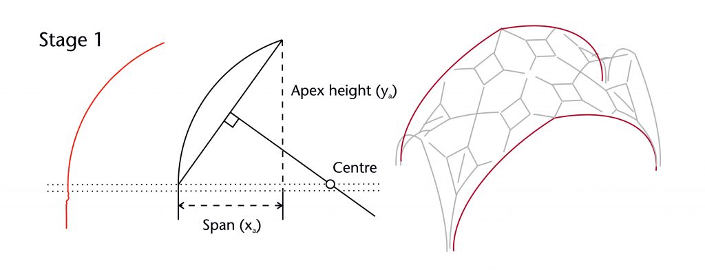
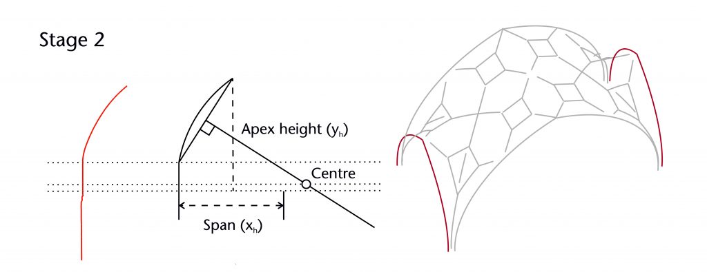
The basic starting point for designing the curvature of any rib was defining its span. This consists of the horizontal distance of the rib along the vault’s plan. It was invariably defined using a combination of the lines drawn on the plan and the profile of the ribs at the springing, providing a single distance between the springing point of the rib and the horizontal position of its apex or end point. At Wells, the position of the springing profile varies considerably from rib to rib, meaning that it must be accounted for individually for each case. For some ribs the span extends between two bosses, meaning that there is no need to take a springing profile into account.
Impost level and springing point
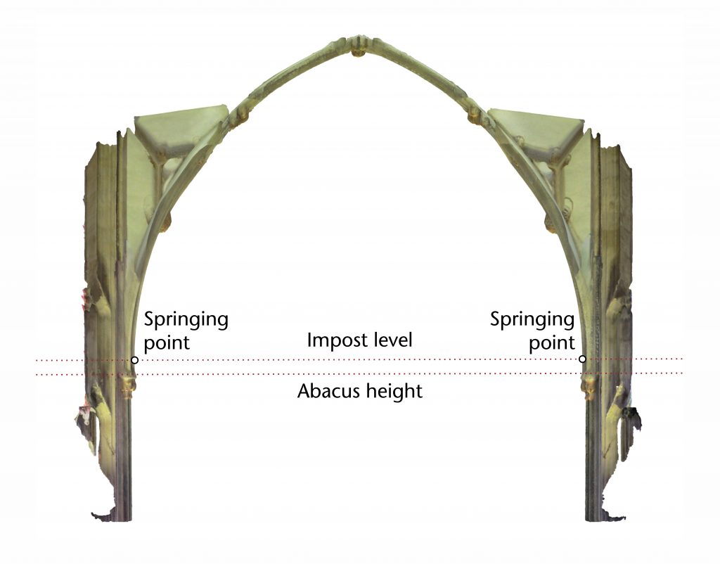
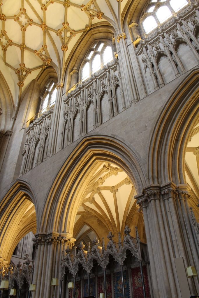
The second fundamental step for any design process was to define the impost level, representing the height of the springing points for the ribs at the corners of the vault. This would usually be positioned at the level of the abacus of the capitals for the supporting columns or shafts, but this was not always the case. In some vaults the impost was slightly below the level of the abacus, resulting in a slight ‘horseshoe’ effect for the ribs. At Wells, however, the decision was taken to make it around 300mm above the abacus, producing a ‘stilted’ effect.
Apex height
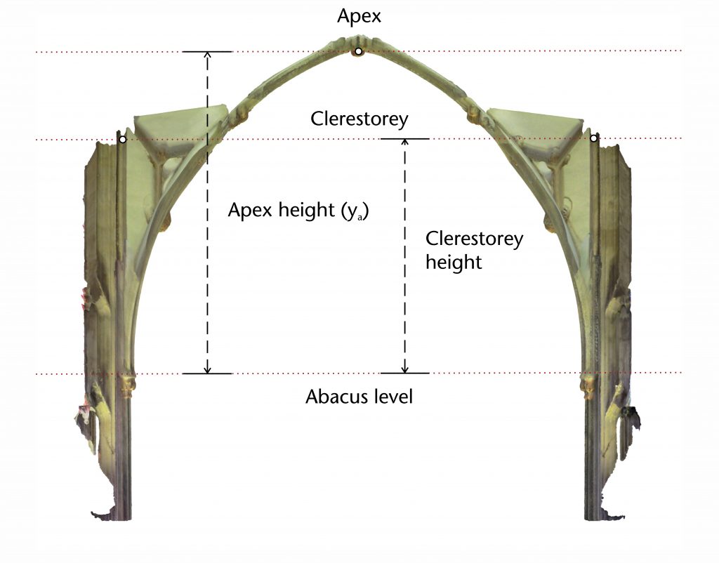
Whilst the apex height of the vault might sometimes be worked out through geometrical means, the usual approach was to define it at the outset. This was most commonly set using heights established by the surrounding architecture. Whilst the apex height of the vault at Wells could have been fixed at the same level as the older work in nave or transept, the designers instead appear to have used the higher apex provided by the east window. This suggests a deliberate attempt to heighten the choir compared to the rest of the structure, a decision which would be in keeping with the hierarchical approach to architectural design which was so common during the Middle Ages.
As for many other vaults of this period, the designers at Wells decided to use this apex height throughout the vault’s longitudinal axis, creating a horizontal ridge of uniform height. However, the apex height of the clerestorey windows on the north and south walls was significantly lower. Such a difference in height was common in medieval architecture, with many clerestories being located above or below the apex of the vault. Any design for the vault at Wells would therefore have to mediate between the two heights, with the specific method selected having several consequences for the process of setting out the ribs.
Rib geometry
The starting point for defining the vault’s ribs depended on both the parameters provided by the surrounding architecture and the more general formal choices that had been made by the designers. At Wells the decision was made to construct the vault around a longitudinal tunnel extending from east to west. The different level of the clerestorey was to be resolved using transverse tunnels that intersected with the main body of the vault.
A conventional option would have been to use the diagonals of the bay to separate the two tunnels, with the disparity in height being managed by either a curved or slanted ridge line extending from the apex of the wall rib to the central boss. However, the plan of the choir vault at Wells did not use the diagonals of the bay for its ribs. The designer instead opted to define the transverse tunnels using the outermost triangles of the plan on the north and south sides. The structure of these tunnels was therefore dependent on how the ribs of the longitudinal tunnel were laid out, which was in turn determined by the geometrical methods employed by their designers.
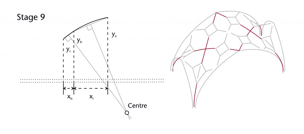
Firstly, a designer would need to define their starting rib. This was often the transverse ribs which extended across the breadth of the bay, especially in vaults arranged around longitudinal tunnels. As the apex heights, springing points and spans of these ribs already been defined, the designers at Wells chose to set out their geometry using the chord method. The same method was also used for the wall ribs on the north and south sides. However, the springing points were stilted far higher than in the transverse ribs. This followed the form set out by the clerestorey, which featured similar stilting for the window arches.
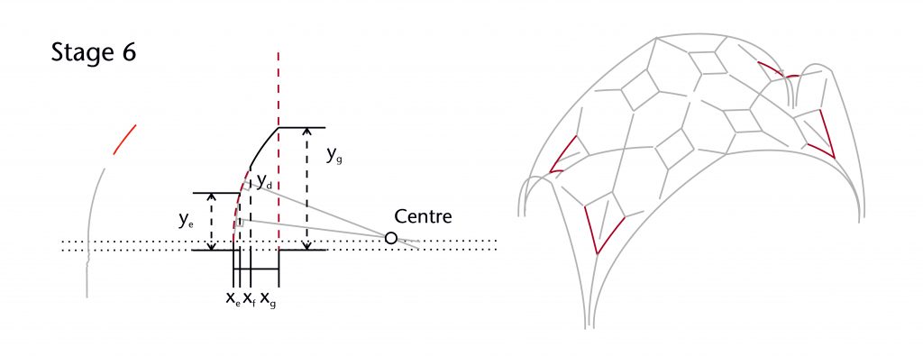
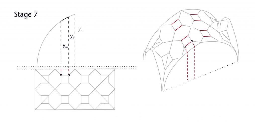
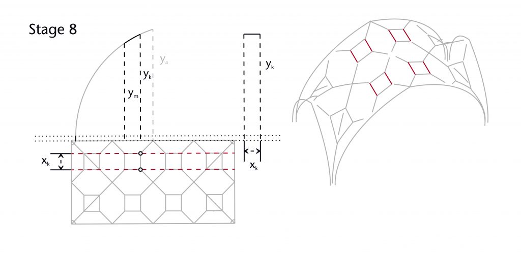
The conventional approach for setting out a longitudinal tunnel of uniform curvature would have been to use the two chord method to define the remaining ribs. However, the inclusion of the squares in the plan at Wells complicated the design process. The designers resolved this by splitting the diagonal ribs of the vault into three distinct sections, each with their own unique curvature. The apex height for each section was defined using the existing geometry of the transverse ribs, an approach which we have called the tunnel method.
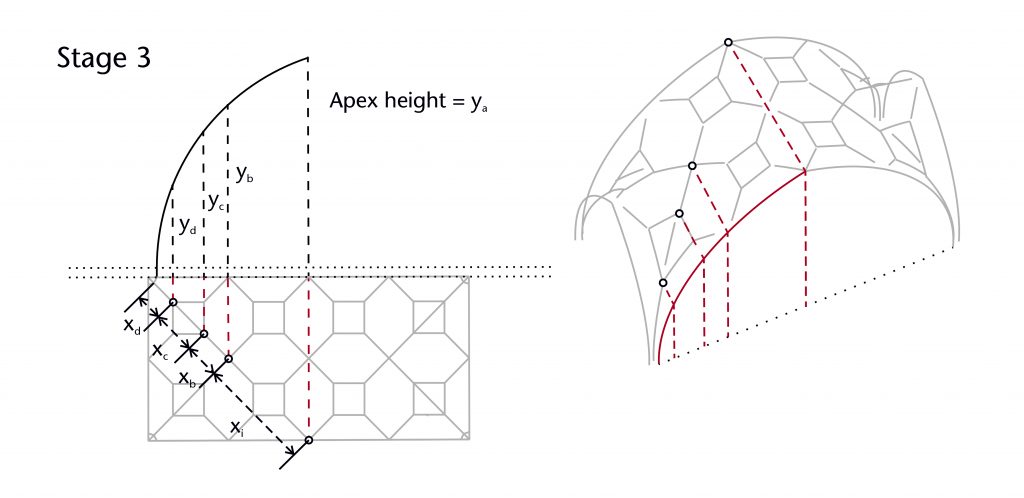
Whereas the upper curve was set out using the two chord method, the lower curve was determined using the chord method. Meanwhile, the middle section which formed the diagonal of the squares was treated as an entirely separate rib, set back from the others and given its own distinctive curvature. This provided more room for the tracery within the vault’s squares, as well as adding a layering effect which increased the decorative variety of the ribbing.
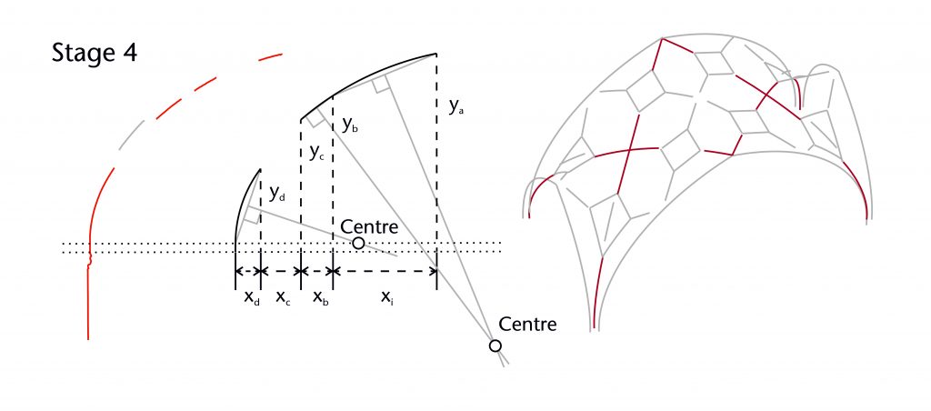
The result was a significant difference in curvature between the transverse and the longitudinal tunnels of the vault. This presented a potential problem when laying out the geometry of the outer sets of squares, as their curvature would need to provide some form of mediation between the two tunnels. This appears to have been accomplished by using a modified, highly specialised variation of the two chord method, continuing the apparent curvature of the lower diagonal into the sides of the square.
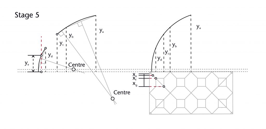
The remaining ribs were set out either by mirroring their counterparts, copying the curvature of the transverse arches or simply using a straight line. As the designer had decided not to use ridge ribs, the tunnels were finished at the apex using a simple ridge line.
Similar processes can be found throughout our case studies. As for the vault plan, the geometry of ribs was established iteratively. Each new rib provided an additional set of fixed elements which allowed further ribs to be devised, gradually narrowing the range of possibilities for the vault’s design. Though the geometry used to define the vault was two-dimensional, the architectural problems which they were used to resolve were fully three-dimensional, requiring a careful consideration of the wider spatial consequences of each decision. Whilst the design process could be highly complex, it was ultimately based on a series of simple steps, each contributing cumulatively to the three-dimensional form of the vault.