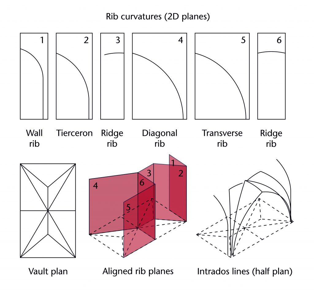
Once the plan of the vault had been worked out, the next stage of design was to set out the geometry of each individual rib. This was accomplished through a variety of different methods, each one consisting of a series of simple geometrical operations. The geometry of each rib was worked out at full scale on a large flat surface, using lines incised into a stone or plaster tracing floor. Consequently, each rib was designed as a curve existing on its own two-dimensional plane, with the three-dimensional form of the vault being created by arranging those planes on the corresponding intrados lines of the existing vault plan. The selection of which geometrical method to use was dependent partially on the existing features of the surrounding building, partially on the decisions made by the designers themselves. By defining specific measurements and other key features in advance, medieval masons were able to create a framework within which the particular geometries of each rib could be worked out, choosing a method appropriate to the limitations imposed by the fabric and their own design decisions.
Fixed elements and variables
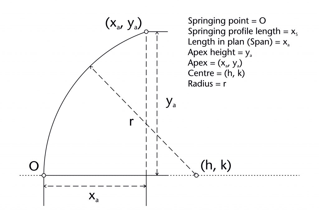
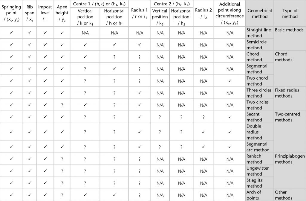
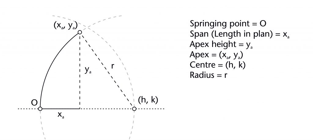
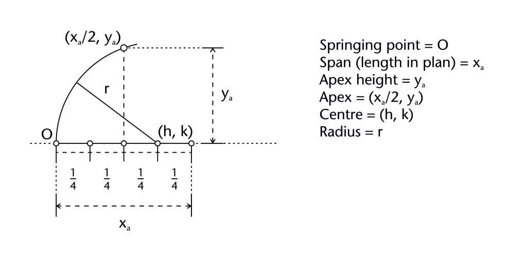
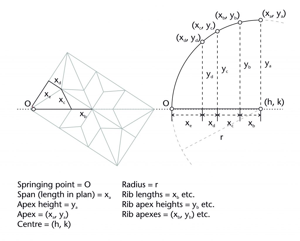
The geometry of almost all the ribs within our case studies was determined using a common set of variables which can be measured using our laser scanning data. Each rib has a springing point (O) and notional apex or end point (xa, ya). The former is usually at the level of the impost (i), defined by the joint between the ribs and the capitals or other supporting structures below. The latter usually represents the apex height of the rib (ya), which was often determined in relation to the features of the surrounding architecture. Though a few ribs are set out as straight lines, the overwhelming majority are curved, possessing at least one radius (r) and centre (h, k). The span of a rib (xa) was invariably determined in advance by its length in plan, with the horizontal position of the springing point being located using the length of the rib profile (xs). The values of each of these variables were mutually interdependent, with any change in one having a direct effect on the values of their others, a principle which can be demonstrated mathematically. By fixing several of these elements in advance, medieval designers were able to determine the remaining values using an appropriate geometrical method without requiring any mathematical calculations. The choice of method was therefore dependent on which variables were defined at the outset, as well as the variables which were still to be determined.
Choosing a method
There were two possible ways for a designer to choose which geometrical method should be used for setting out a particular rib. The first was to select a method on the basis of which elements had already been fixed by other aspects of the surrounding building. Each of the geometrical methods which we have identified relied on the presence of a specific combination of starting variables. For example, if the apex height of a rib (ya) was already fixed by the height of the window arch below, then one of the chord methods would be a logical way of setting out its curvature. The second way was to choose a method in accordance with a particular design decision. For example, if the designer wished to maintain the same radius (r) throughout the vault, they might prefer to use one of the fixed radius methods such as the three circles or two circles method. Sometimes this would require defining an additional variable to set out the rib. For example, if the designer wanted to give the effect of a continuous tunnel throughout the vault, they could make use of the two chord method. However, it would first be necessary for them to define an additional point along the circumference of the rib (xb, yb).
Designing a rib’s curvature was not therefore simply a matter of selecting a method to suit a particular set of fixed elements. Whilst defining an apex height (ya) or radius (r) might reduce the range of possibilities available to a designer, it would rarely restrict their choices to a single option. Sometimes it was the method itself which would dictate the elements which needed to be fixed in advance, whilst on other occasions it was a mixture of both. Consequently, its is not possible to generalise regarding how geometrical methods were chosen during this period. Instead, the design process for every rib must be considered on a case-by-case basis.
Geometrical methods
The following are the geometrical methods which we have found in our case studies:
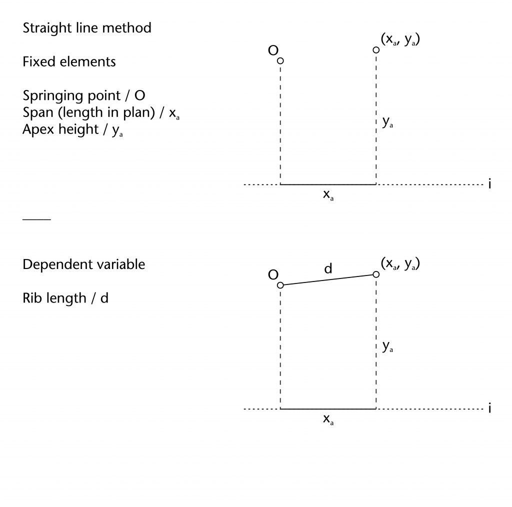
Straight line method
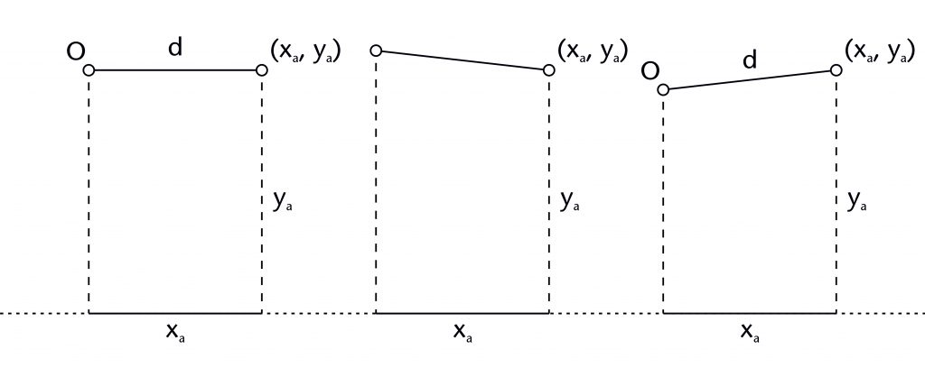
This is the most basic method of setting out a rib, involving drawing a straight line from the springing point (O) to the end point (xa, ya). It was usually used for ridge ribs, often providing a single longitudinal ridge down the central axis of the vault.
Fixed Elements
Springing point (O)
Apex height (ya)
Span (xa)
Dependent variables
Rib length (d)
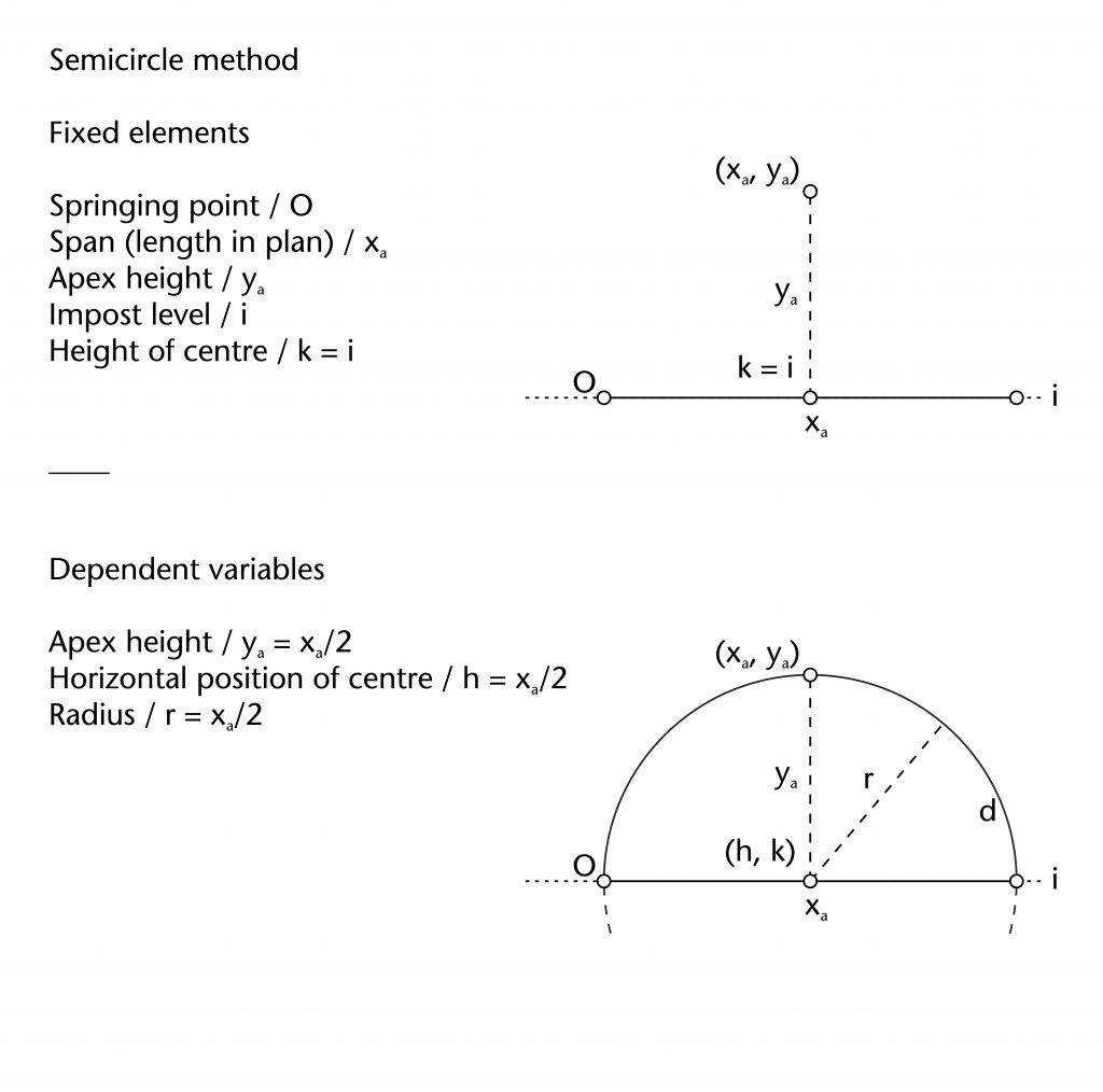
Semicircle method
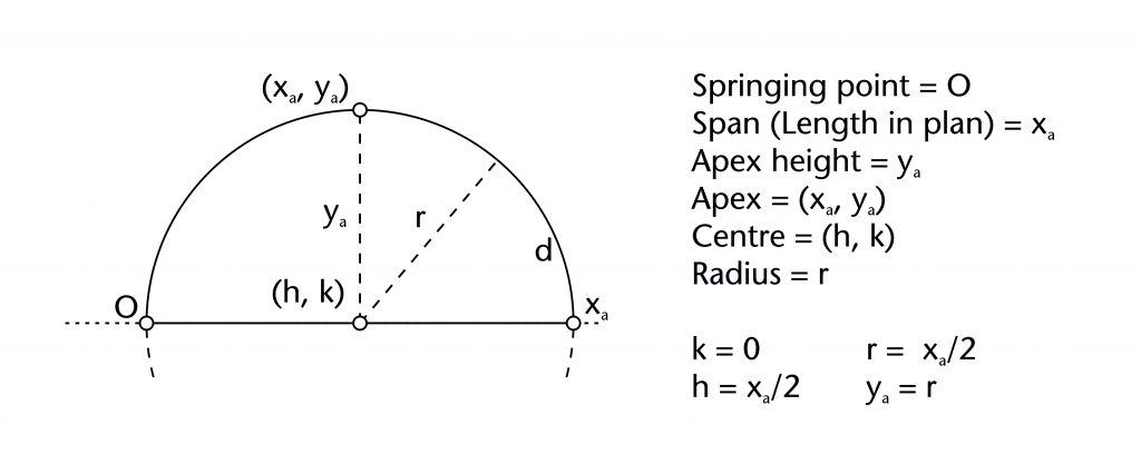
This method involves setting out a rib as a semicircular arc centred on the midpoint of the span (h = xa/2; k = 0) and passing through both of its springing points (O and (xa, 0)). The apex height (ya) and radius (r) are therefore both equivalent to half the span of the rib (xa/2).
Fixed Elements
Springing point (O)
Span (xa)
Position of centre (h, k)
Dependent variables
Apex height (ya)
Radius (r)
Chord methods
These methods all revolve around drawing chords and constructing their perpendicular bisectors. A chord is a straight line between two points along the circumference of a circle. The perpendicular bisector of a chord will always pass through the centre of a circle (h, k). By fixing the start and end points of the chord and plotting the points of intersection between their perpendicular bisectors and other defined features of the vault, designers were able to set out both the centre and radius of the ribs.
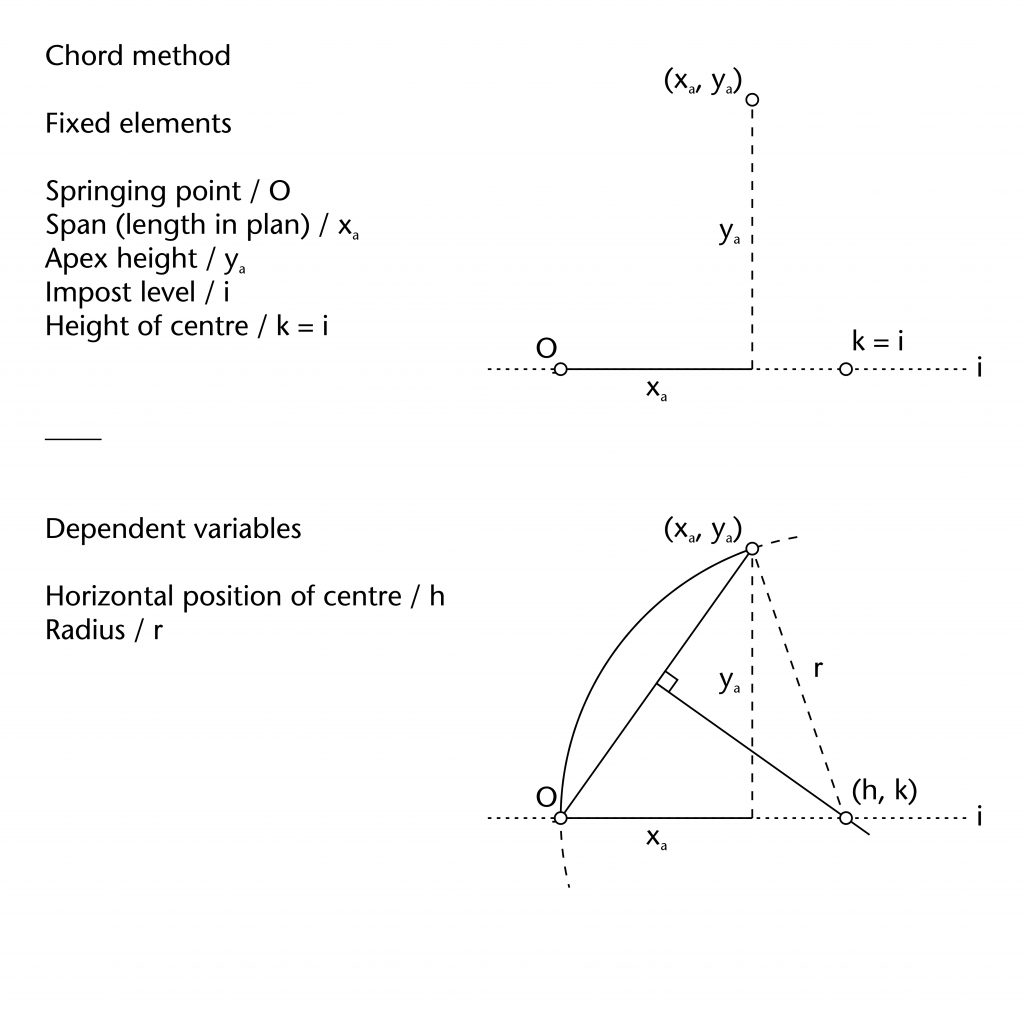
Chord method
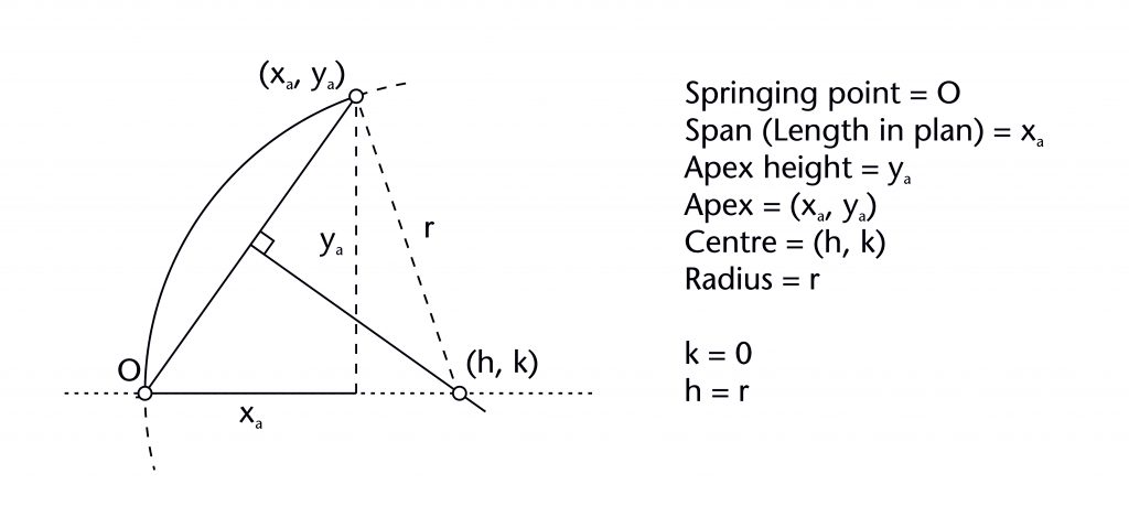
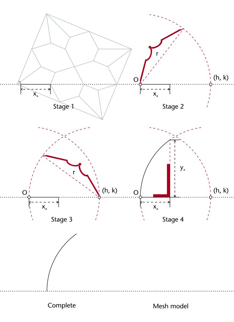
The chord method involves drawing a straight line between the defined springing (O) and apex points (xa, ya) of the rib. The horizontal position of the centre (h) is determined by identifying the point of intersection between the perpendicular bisector of this chord with the impost line, effectively fixing the height of the centre at the level of the impost (k = 0). Once the horizontal position of the centre is found, the radius (r) is also defined and the curvature of the rib can be drawn into place.
Fixed elements
Springing point (O)
Apex height (ya)
Span (xa)
Height of centre (k)
Dependent variables
Horizontal position of centre (h)
Radius (r)
More information
The chord method can be set out using the following steps:
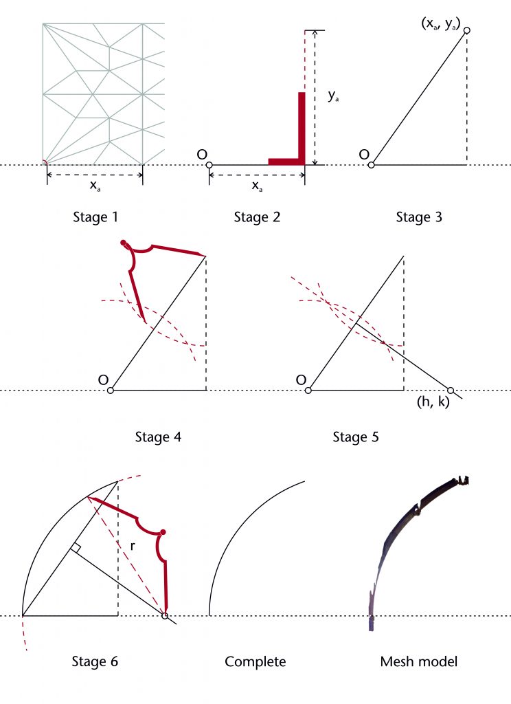
The chord method is often modified by changing the level of the impost (i), usually by raising the springing point of the rib through a process called stilting. In some cases, the resulting geometry can also be altered by fixing the height of the centre (k) at a level above or below that of the impost. This is accomplished by drawing an additional horizontal line parallel to the impost at the appropriate height, providing a new point of intersection for the perpendicular bisector of the chord.
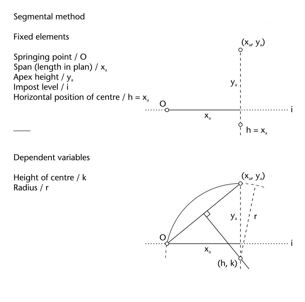
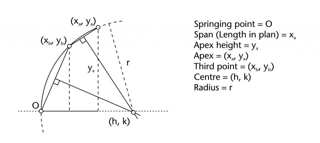
Segmental chord method
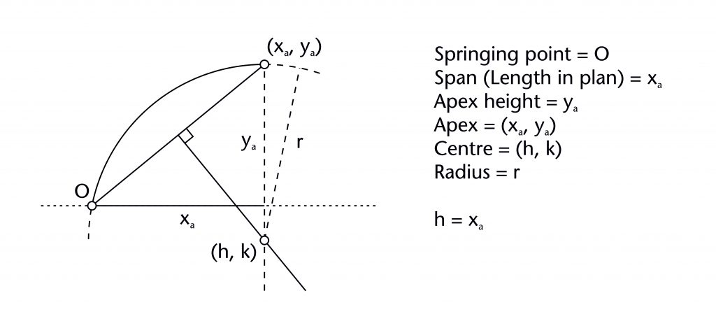
The segmental chord method is a variation on the chord method which can be used to set out segmental arches. As in the chord method, a straight line is drawn between the defined springing (O) and apex points (xa, ya) of the rib. However, rather than fixing the height of the centre (k) at the level of the impost, the designer instead fixes its horizontal position (h) using the length in plan (xa). The height of the centre (k) is determined by identifying the point of intersection between the perpendicular bisector of the chord with a vertical line extending down from the apex of the rib (xa, ya). Once the height of the centre is found, the radius (r) is also defined. The result was a curvature with a centre below impost level, passing through both the springing point and the apex.
Dependent variables
Height of centre (k)
Radius (r)
Fixed elements
Springing point (O)
Apex height (ya)
Span (xa)
Horizontal position of centre (h)
More information
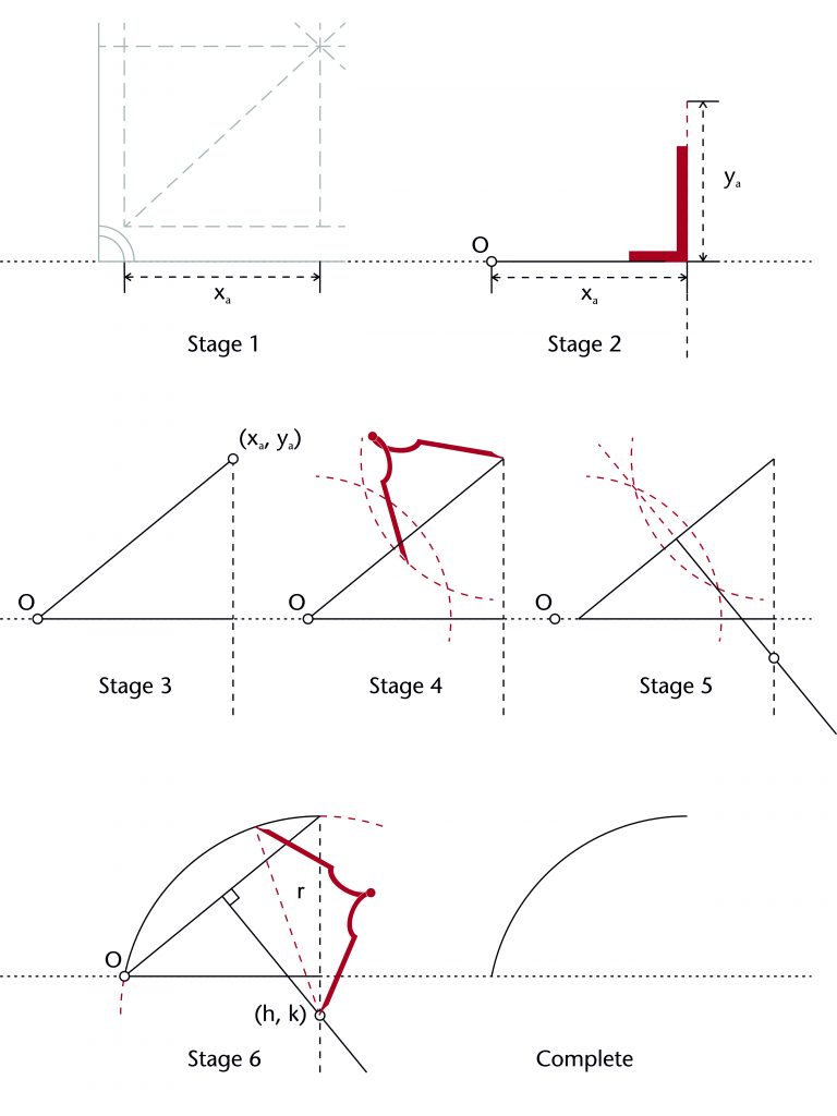
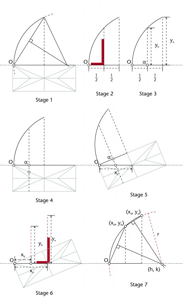
The segmental chord method can be set out using the following steps:
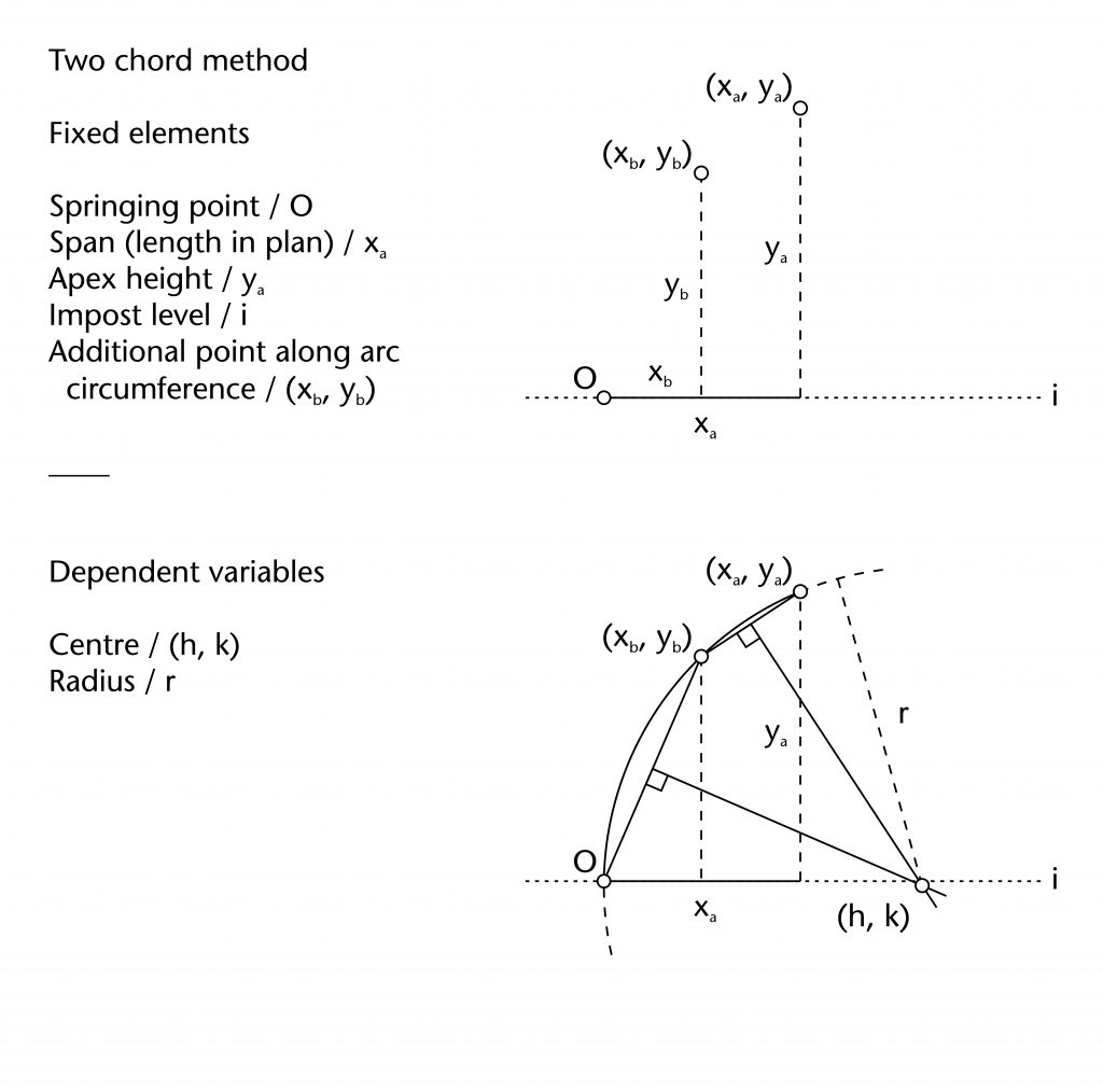
Two chord method
The two chord method is based on the principle that the centre of any circle can be defined using three points along its circumference. This was well understood during the Middle Ages, as demonstrated by its appearance and in the thirteenth-century Villard de Honnecourt manuscript. For the two chord method, these three points were provided by the springing (O), apex (xa, ya) and an additional point (xb, yb) defined by the designer through a variety of geometrical processes. A chord was drawn between the springing and additional point, as well as the additional point and the apex. The centre of the rib (h, k) was determined by identifying the point of intersection between the perpendicular bisectors of the two chords, defining the radius (r) in the process.
Fixed elements
Springing point (O)
Apex height (ya)
Span (xa)
Third point (xb, yb)
Dependent variables
Height of centre (k)
Horizontal position of centre (h)
Radius (r)
More information
The two chord method can be set out using the following steps:
The main advantage of this method is that it allows the curvature of one rib to be transferred horizontally, meaning that the second rib will have a similar curvature when viewed in profile. This feature was often used to create a tunnel effect along the longitudinal or transverse axis of the vault. The ‘tunnel method’ involved using the curvature of a transverse or longitudinal rib to define the third point (xb, yb) along the remaining ribs in the tunnel. This could be defined either by its horizontal or vertical position. The former can be accomplished using a line perpendicular to the impost at a point defined on the vault plan (a) to derive its height (yb), the latter using a line parallel to the impost located at the predefined height (yb). Using the vault plan, the position of this point can then be projected horizontally onto the next rib, defining its horizontal position along the rib’s span (xb). The two chord method can then be completed as normal, with the third point being located using its defined height (yb) and horizontal distance from the springing (xb).
Fixed radius methods
These methods all revolve around transferring the radius (r) from one rib to another. This approach has the advantage that it allows the same radius to be used for several ribs within the vault, potentially reducing the range of different parts which masons had to cut from the stone. The radius would be defined using a variety of different methods, usually involving some kind of generator rib. Whilst it has often been assumed that the generator was normally the diagonal ribs of the vault, this does appear to have been the case for many of our case studies. Instead, designers often used a transverse or longitudinal rib, with the radius being defined using the chord method.
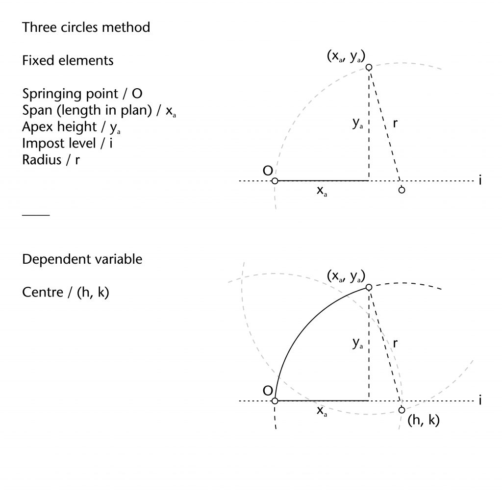
Three circles method
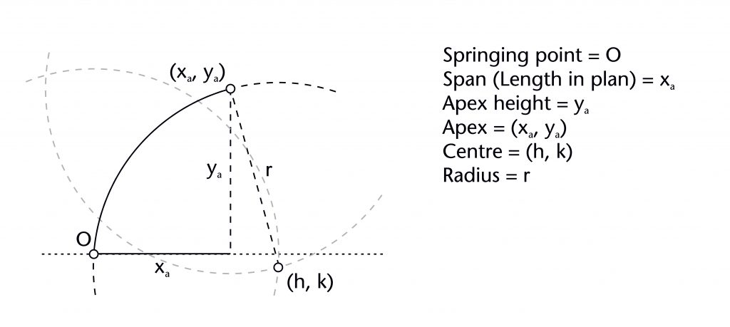
The three circles method involves drawing two circles of the same radius (r), the first centred on the springing point (O) and the second on the apex point (xa, ya) of the rib. The centre (h, k) is defined using the lower point of intersection between these two circles. This can then be used to draw a third circle of the same radius (r), providing the curvature for the rib.
Fixed elements
Springing point (O)
Apex height (ya)
Span (xa)
Radius (r)
Dependent variables
Height of centre (k)
Horizontal position of centre (h)
More information
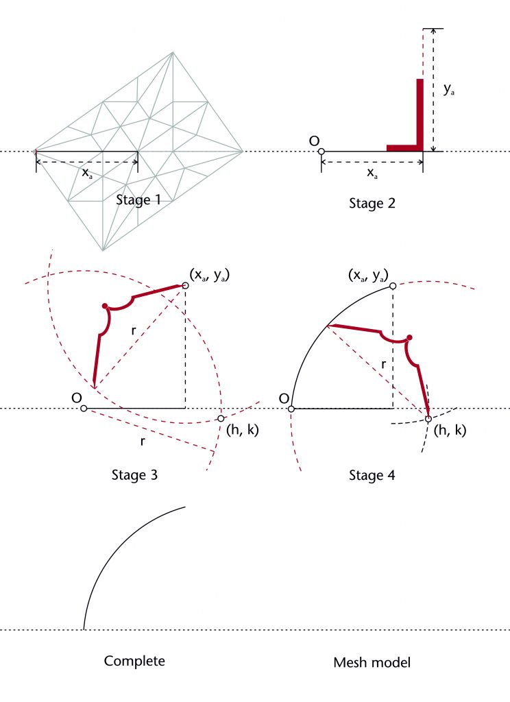
The three circles method can be set out using the following steps:
Whilst the method can be used to transfer a radius between ribs, it cannot be used to generate them. Its presence within a vault therefore always implies the use of an alternative geometrical method for defining the starting radius. The specific method used for this could vary considerably from vault to vault. In many cases the chord method was used, as this was the most straightforward means of defining a radius. However, this was not the only option available to medieval designers, and many scholars have identified alternative approaches in continental vaults such as the Prinzipalbogen methods.
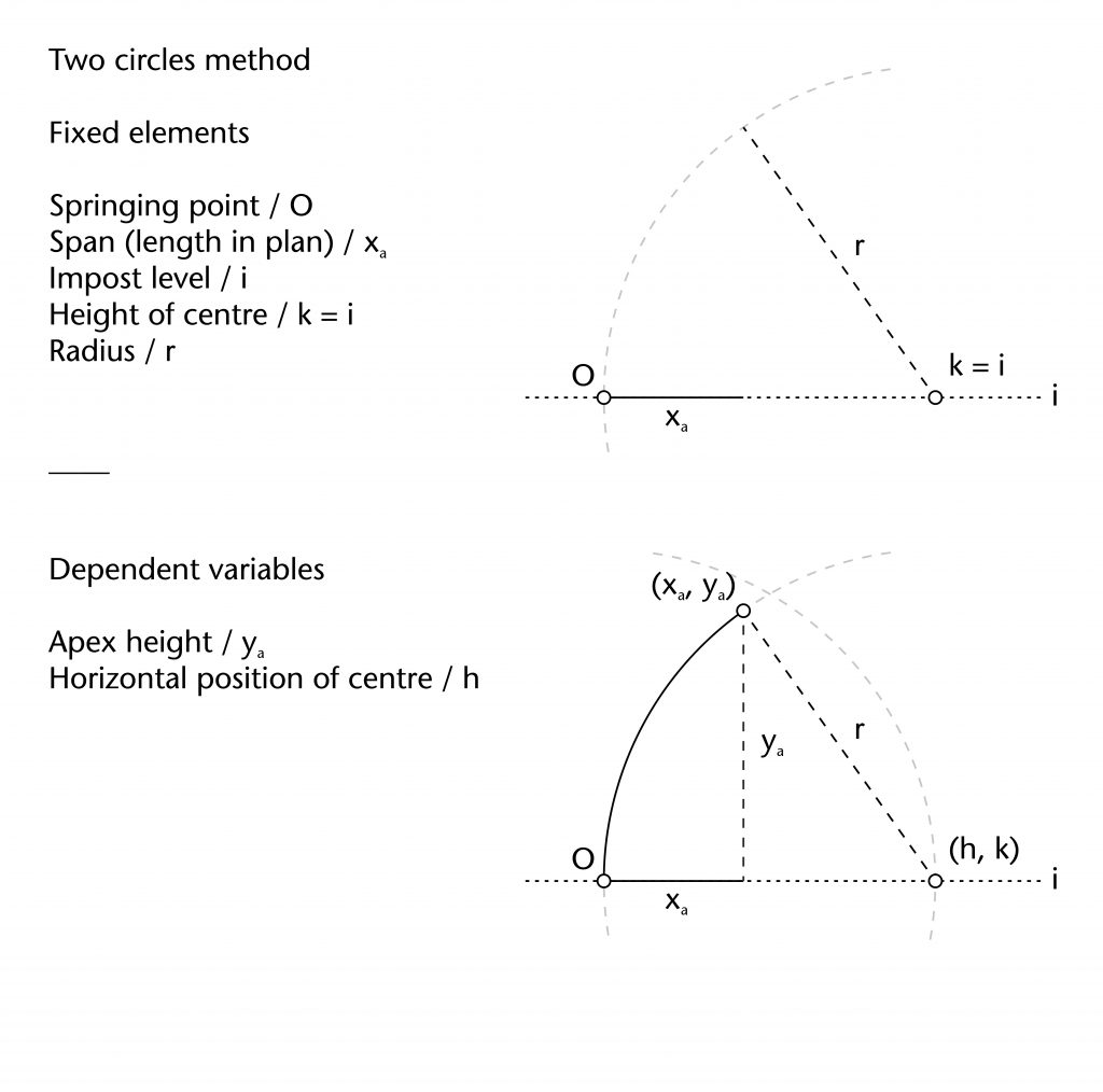
Two circles method
The two circles method is a method for reusing a shared radius in situations where the apex height of the rib is unknown. A circle of the defined radius is drawn centred on the springing point (O). The horizontal position of the centre (h) is defined by the circle’s point of intersection with the impost line (h = r), effectively fixing the centre’s height at the level of the impost (k = 0). A line perpendicular to the impost is drawn through the end point of the rib’s span (xa). A second circle is then drawn centred on (h, k), its point of intersection with the perpendicular line providing the missing apex height (ya).
Fixed elements
Springing point (O)
Height of centre (k)
Span (xa)
Radius (r)
Dependent variables
Horizontal position of centre (h)
Apex height (ya)
More information
The two circles method can be set out using the following steps:
The method was useful for managing the three-dimensional shapes of more complex vault patterns, in particular lierne vaults where the ribs do not all converge on a ridge of uniform height. By using the two circles method, the radius could be transferred from rib to rib without have to define a height for each individual point on the vault plan. This was a simple and effective means of providing a stepped structure to the vault, giving a more rounded and open shape to its overall curvature.
Two-centred methods
Not all of the ribs within our case studies were constructed using a single-centred arc. Multicentred ribs have a more complex curvature than single-centred ones and a far more difficult to analyse geometrically. Two-centred arcs seem to be the most common type within our case study sites, though it is not always clear how many centres were used in a single rib. There were several methods which medieval designers could use to design two-centred ribs, usually consisting of a hybrid between fixed radius and chord methods.
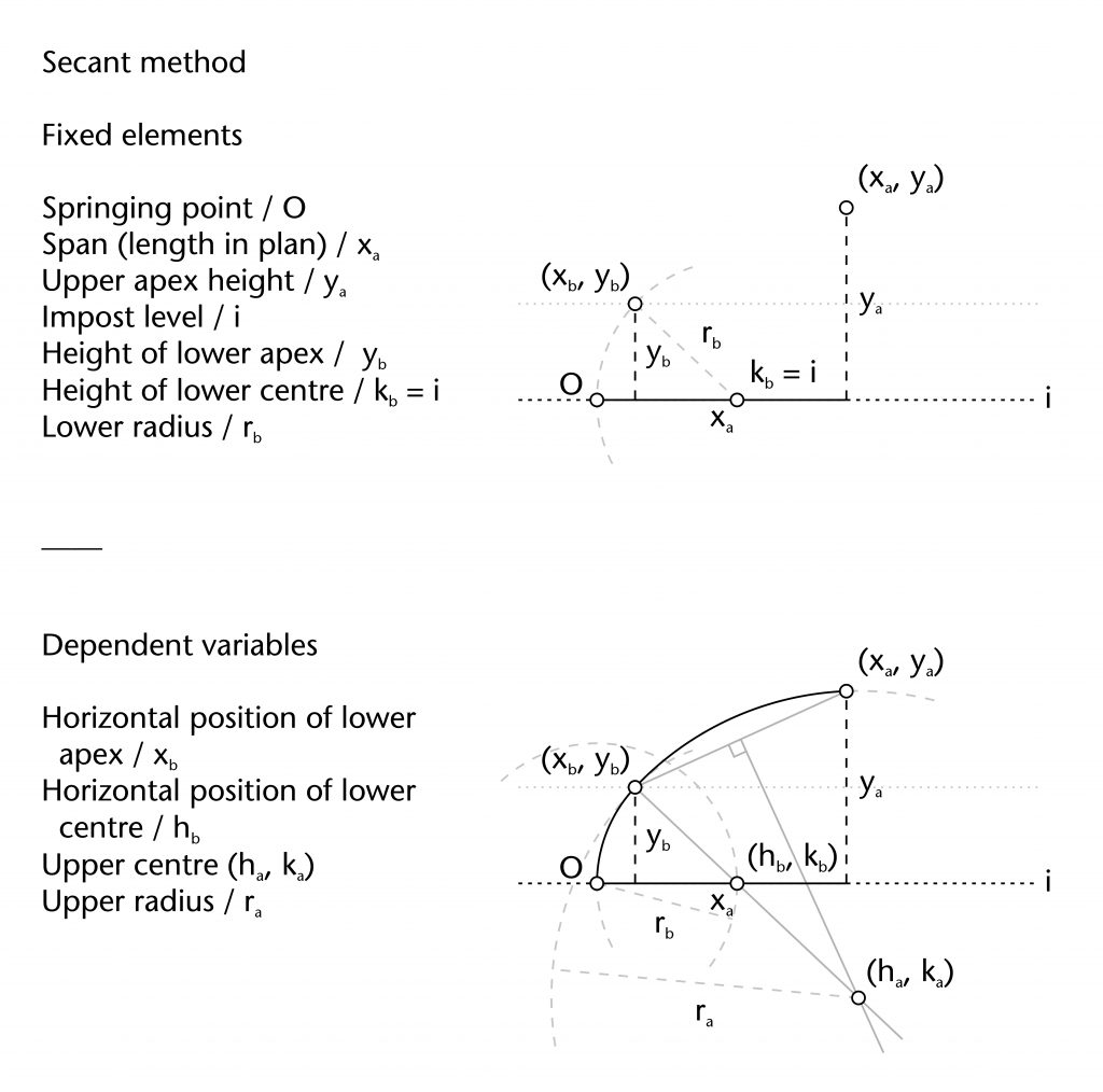
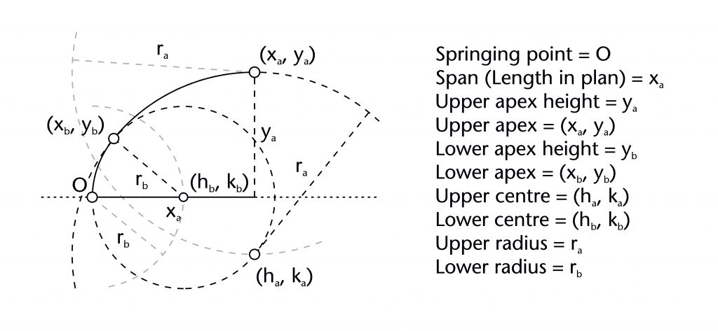
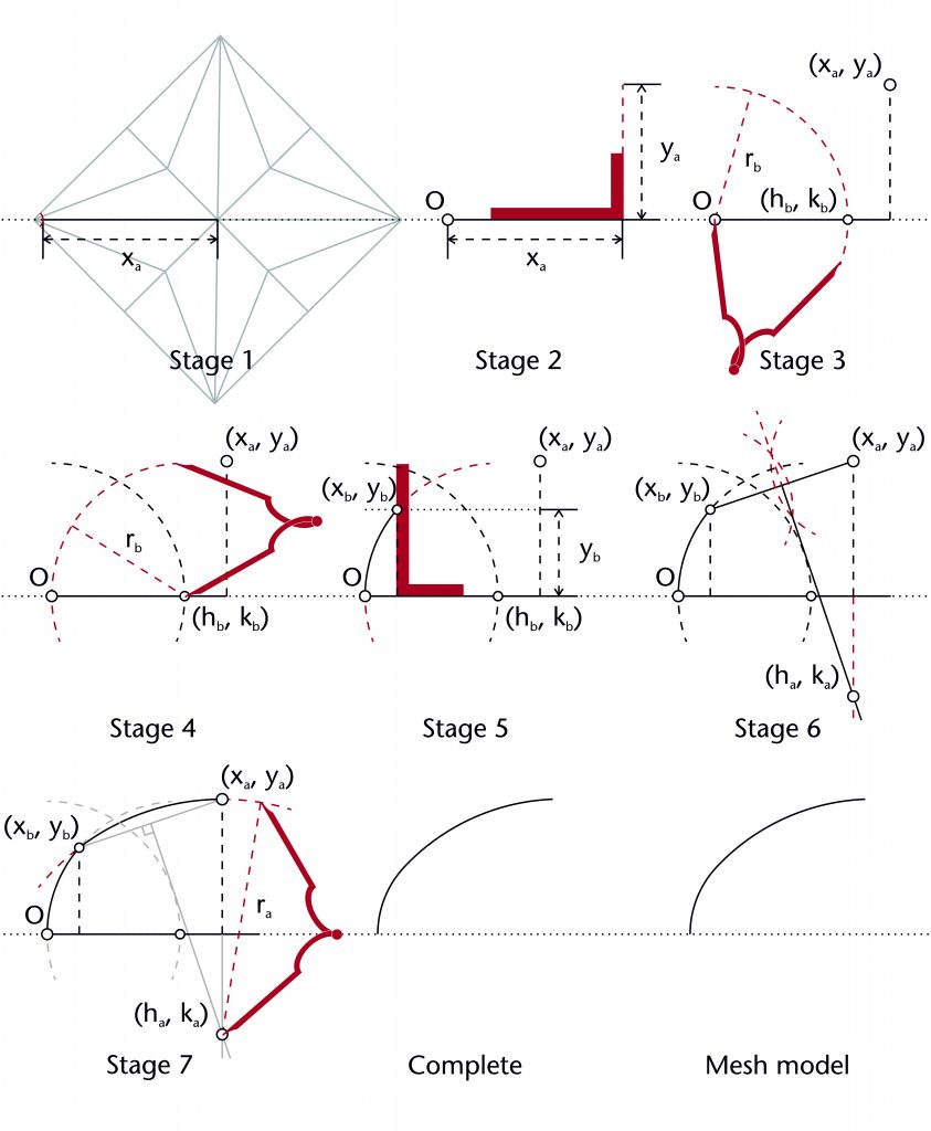
Secant method
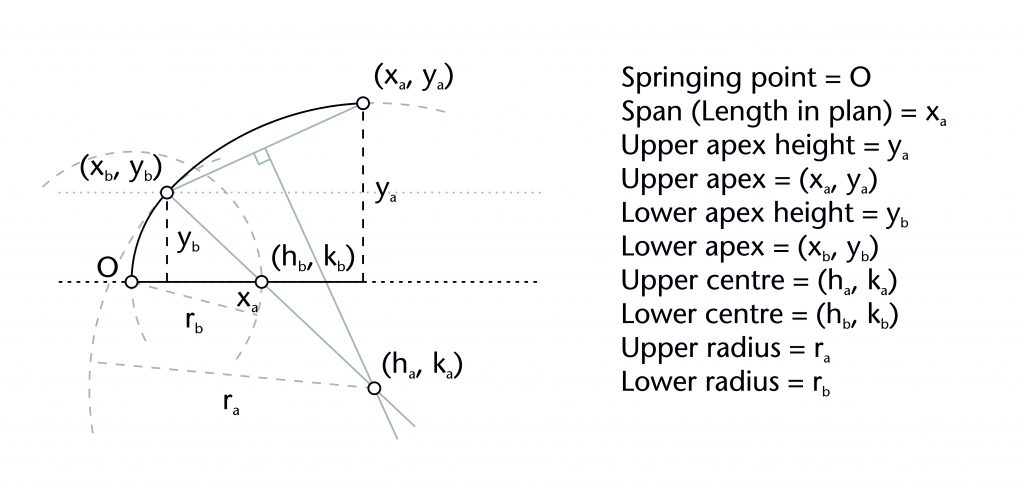
The secant method is one of two potential methods proposed by Robert Willis (1800-75) for setting out the geometry of two-centred arcs. The first stage involves setting out the lower arc using a variation on the two circles method. A circle with a defined radius (rb) is drawn centred on the springing point (O). The horizontal position for the centre of the lower arc (hb) is defined by the circle’s point of intersection with the impost line (hb = rb), effectively fixing the centre’s height at the level of the impost (kb = 0). A second circle of the same radius (r) is then drawn centred on (hb, kb), defining the curvature of the lower arc. A horizontal line is then drawn parallel to the impost at predefined height (yb), allowing the point of transition between the upper and lower arcs (xb, yb) to be identified.
Once this stage has been completed, a straight line is drawn through the point of transition (xb, yb) and the centre of the lower arc (hb, kb), forming a ‘secant’ across the diameter of the circle. A chord is then drawn between the point of transition (xb, yb) and the apex of the rib (xa, ya). The position of the centre for the upper arc (ha, ka) is determined by identifying the point of intersection between the perpendicular bisector of this chord and the secant drawn previously. Once the position of the centre has been found, the upper radius (ra) is also defined and the curvature of the upper arc can be drawn into place.
Fixed elements
Springing point (O)
Apex height (ya)
Span (xa)
Height of transition (yb)
Height of lower centre (kb)
Lower radius (rb)
Dependent variables
Horizontal position of transition (xb)
Horizontal position of lower centre (hb)
Position of upper centre (ha, ka)
Upper radius (ra)
More information
The secant method can be set out using the following steps:
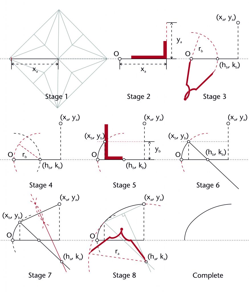
A principal advantage of this method is that it would have ensured a smooth transition between the lower and upper arcs of the rib. This is because the two arcs will have the same curvature at the point of transition (xb, yb), meaning that there would be no kinks or cusps in the rib’s intrados line.
There are several possible variations of the secant method. The curvature of the lower arc could also be defined using the chord or three circles method. However, this would require the horizontal and vertical position of the point of transition (xb, yb) to be defined in advance, perhaps using a variation on the tunnel method. The location of the point of transition could also be determined using its horizontal position along the span (xb) rather than its height (yb).
Though there are one or two sites where it is possible that the secant method was used, these are usually cases where the double radius method could also have been used. It is therefore difficult to identify whether or not the secant method was used by medieval designers.
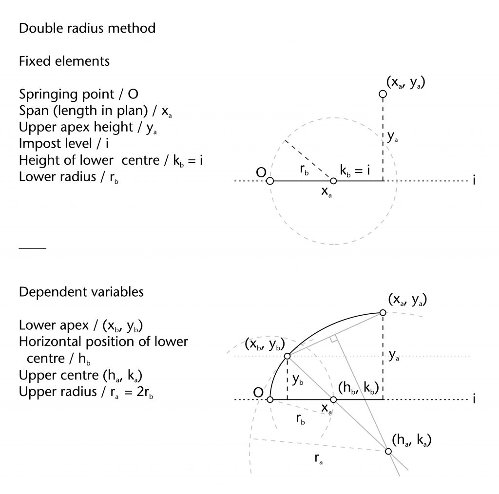
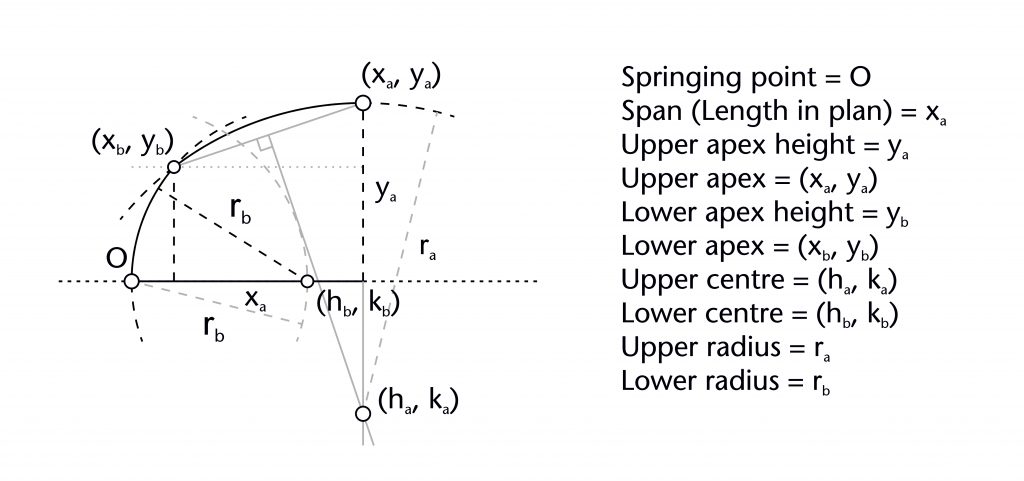
Double radius method
The double radius method is one of the two possible methods proposed by Robert Willis (1800-75) for setting out the geometry of two-centred arcs. The first stage involves setting out the lower arc using a variation of the two circles method. A circle with a defined radius (r) is drawn centred on the springing point (O). The horizontal position for the centre of the lower arc (hb) is defined by the circle’s point of intersection with the impost line (hb = rb), effectively fixing the centre’s height at the level of the impost (kb = 0). A second circle of the same radius (rb) is then drawn centred on (hb, kb), defining the curvature of the lower arc. The point of transition between the two arcs is located by drawing a line parallel to the impost at a predefined height (yb) and identifying its point of intersection with the second circle (xb, yb).
Once this stage has been completed, a variation on the three circles method is used to define the curvature of the upper arc. A third circle is drawn with a radius (ra) double that of the lower arc (ra = 2rb), centred on the apex of the rib (xa, ya). The centre for the upper arc (ha, ka) is defined using the lower point of intersection between this new circle and the circle centred on (hb, kb). This can then be used to draw a fourth circle of radius (ra), providing the upper arc for the rib.
Fixed elements
Springing point (O)
Apex height (ya)
Span (xa)
Height of lower centre (kb)
Lower radius (rb)
Dependent variables
Point of transition (xb, yb)
Horizontal position of lower centre (hb)
Position of upper centre (ha, ka)
Upper radius (ra)
More information
The double radius method can be set out using the following steps:
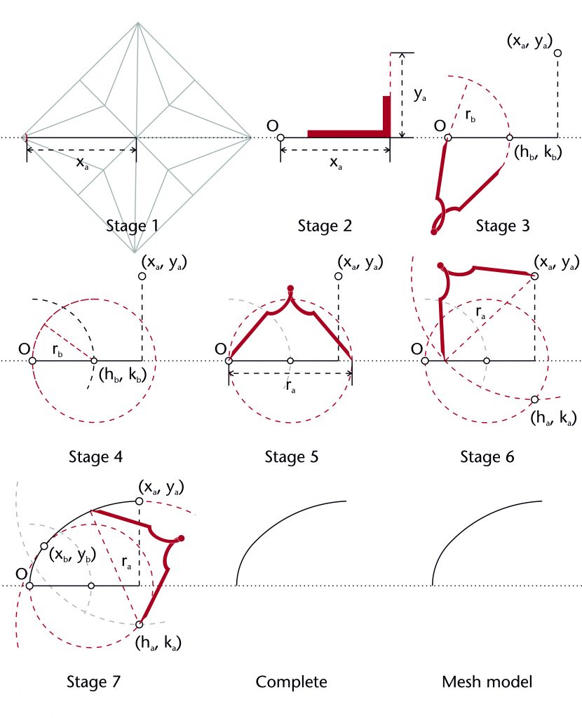
A principal advantage of this method is that it would have ensured a smooth transition between the lower and upper arcs of the rib. This is because if one circle with a radius equal to the other’s diameter is centred along the circumference of the smaller circle, then both circles will always have the same curvature at their point of intersection. The result is that there would be no kinks or cusps in the curvature of the rib.
As for the other two-centred methods, the lower radius (rb) would need to be defined in advance. One possibility is that it was initially defined using the chord method. However, this would also have required the horizontal and vertical position of the point of transition (xb, yb) to be a fixed element, perhaps using a variation on the tunnel method.
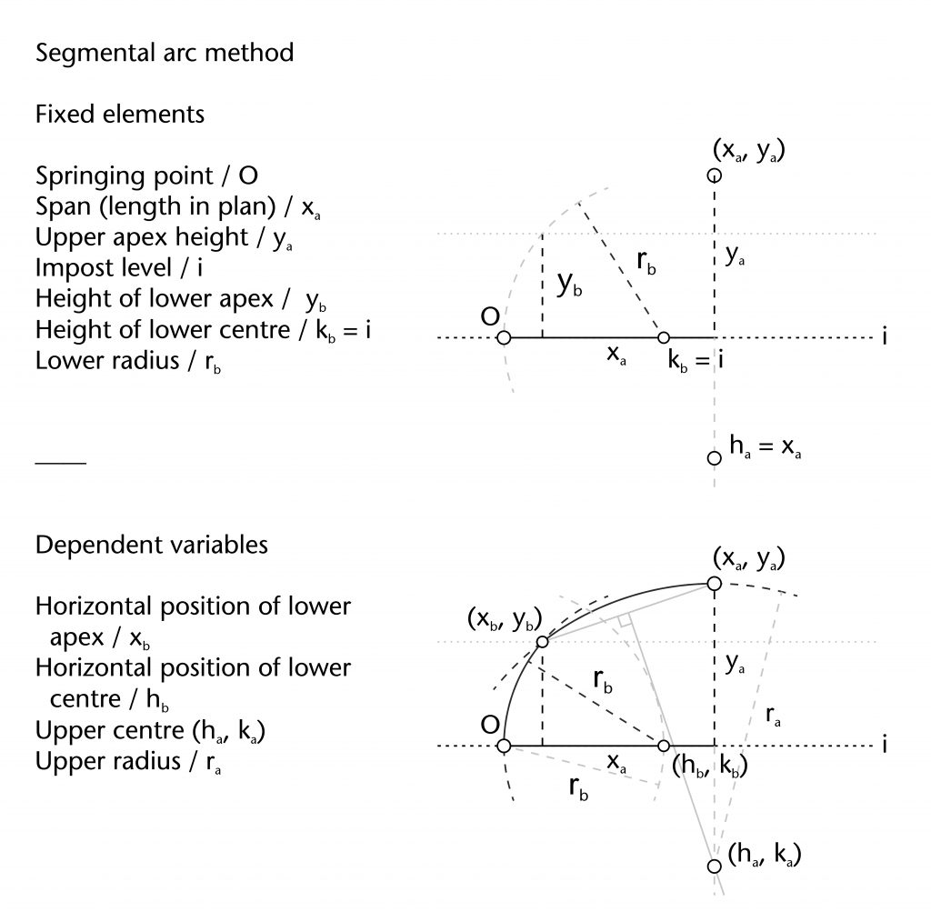
Segmental arc method
The segmental arc method is a comparatively simple approach to the problem of setting out two-centred ribs. The first stage involves setting out the lower arc using a variation on the two circles method. A circle with a defined radius (rb) is drawn centred on the springing point (O). The horizontal position for the centre of the lower arc (hb) is defined by the circle’s point of intersection with the impost line (hb = rb), effectively fixing the centre’s height at the level of the impost (kb = 0). A second circle of the same radius (rb) is then drawn centred on (hb, kb), defining the curvature of the lower arc. The point of transition between the two arcs is located by drawing a line parallel to the impost at a predefined height (yb) and identifying its point of intersection with the second circle (xb, yb).
Once this stage has been completed, the curvature of the upper arc would be defined using a segmental arc. A chord is drawn between the point of transition (xb, yb) and the apex of the rib (xa, ya). The position of the centre for the upper arc (ha, ka) is determined by identifying the point of intersection between the perpendicular bisector of this chord and a line perpendicular to the impost passing through the apex (xa, ya). Once the position of the centre has been found, the radius (ra) is also defined and the curvature of the upper arc can be drawn into place.
Fixed elements
Springing point (O)
Apex height (ya)
Span (xa)
Height of transition (yb)
Height of lower centre (kb)
Lower radius (rb)
Dependent variables
Horizontal position of transition (xb)
Horizontal position of lower centre (hb)
Position of upper centre (ha, ka)
Upper radius (ra)
More information
The segmental arc method can be set out using the following steps:
Whilst it is more straightforward than the other methods for constructing two-centred arcs, the resulting ribs will always have a kink or cusp in their curvature. This could be addressed in a number of ways by the masons, either through inserting a specially shaped block to smooth out the transition or simply leaving the cusp unchanged. Even in cases where the segmental arc method was used, the point of transition between the two curvatures is difficult to discern with the naked eye and can only be detected through detailed geometrical analysis.
Other methods
There are also several additional methods which have been identified by other scholars, but which have not yet been found in our case studies:
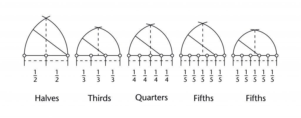
Arch of points
The arch of points is a method for constructing pointed arches by dividing their span into a series of equal parts. This involves taking the full span of the arc (xa) and splitting it into fractions, defining a series of points along the impost line. These points could then be used as the centre (h, k) for the rib on either side of the arch, allowing the radius (r) to be defined and the curvature to be drawn into place. The apex of the pointed arch (xa, ya) is derived from the point of intersection between the two curves.
Fixed elements
Springing point (O)
Span (xa)
Number of divisions (n)
Height of centre (k)
Dependent variables
Horizontal position of centre (h)
Radius (r)
Apex height (ya)
More information
There are a wide variety of different arches of points which can be defined using this method. The most straightforward is to use the springing points as centres for constructing the arch. However, by using other points along the span it is possible to produce different apex heights. For divisions of thirds and quarters there is only one alternative pair of points which could be used, but for fifths or higher there would be more and more different ways of defining centres for the ribs.
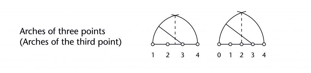
Whilst the technique was known during the Middle Ages, as shown by its appearance in the Villard de Honnecourt manuscript, it does not seem to have been used in any of our case studies. It is also not clear how an arch of points should be described, as it depends on how the individual points are numbered. For some scholars an arch of the third point would refer to an arch divided into quarters along its span, whereas for others it would be thirds. In both cases, however, the fundamental principle for determining the arch would be the same.
Prinzipalbogen
The Prinzipalbogen is a group of related fixed radius methods which revolve around using a principal arch to define the curvature for all of the ribs within the vault. This ‘Prinzipalbogen’ is almost invariably some form of diagonal, which usually has the largest span of all the ribs in the vault. The differences between each method consist of how the radius of the Prinzipalbogen is defined and what specific techniques were used to transfer it throughout the ribs of the vault.
Ranisch method
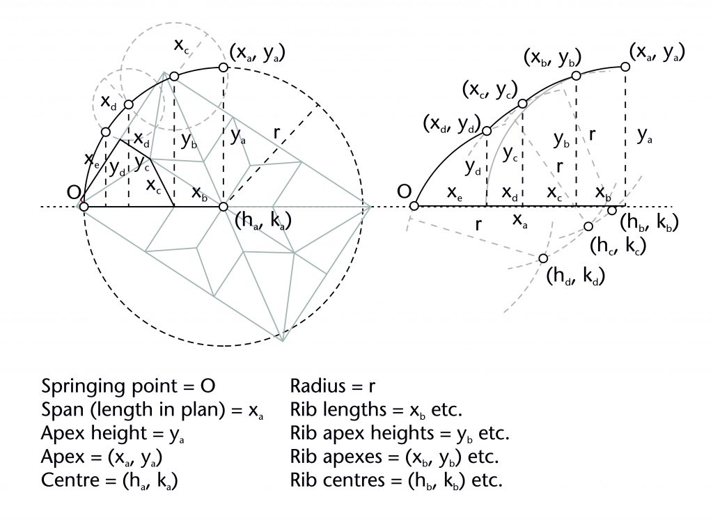
The first Prinzipalbogen method to be identified was proposed by the civic architect Bartel Ranisch (1648-1702). The first stage is to construct the principal arch using the span (xa) of the vault’s diagonal. A circle is drawn centred on the end point of the diagonal’s horizontal length (xa, 0), its circumference passing through the springing point (O). This produces a semi-circular arc with a radius equal to the span (r = xa), providing the curvature for all of the remaining ribs as well as the apex height of the vault (ya = r). A sequence of ribs is then worked out, consisting of a wandering path leading from the highest to the lowest desired apex for each rib in the vault. For any apex located along the line of the diagonal, the span of the rib (xb) is used to position a perpendicular line along the impost. Its point of intersection with the principal arch gives a height for its springing point (xa, ya) as well as the curvature of the rib.
For any ribs subsequent which deviate from the diagonal, the process is more complex. The span of the rib (xc) is used as the radius for a circle centred on its apex point (xb, yb). The point of intersection between this circle and the principal arch gives an apex height for springing point of the rib (yc). The three circles method can then be used to define the curvature of the rib. This process is then repeated as many times as necessary until all of the ribs in the wandering path have been defined.
Fixed elements
Springing point (O)
Diagonal apex height (ya)
Diagonal span (xa)
Rib spans (xb, xc, xd etc.)
Principal arc centre (xa, 0)
Dependent variables
Rib apex heights (yb, yc, yd etc.)
Radius (r)
More information
The Ransich Prinzipalbogen method can be set out using the following steps:
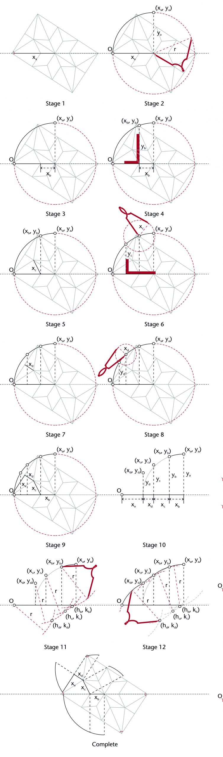
Ranisch derived this method from his extensive study of the churches in area surrounding his home city of Gdansk in Poland, publishing his research in his Beschreibung aller Kirchengebäude der Stadt Dantzig of 1695. This treatise is the earliest known use of the term Prinzipalbogen, though he also used the terms ‘Haupt-Bogen’ or ‘Quadrant’. As many of the churches which he studied have since been destroyed or reconstructed (some by Ranisch himself), it is difficult to assess the accuracy of his conclusions. However, those which do survive suggest that his proposed method is at least possible.
Ungewitter method
An alternative interpretation of the Ranisch Method was proposed by the architect Georg Gottlob Ungewitter (1820-64). The first stage is to construct the principal arch using the span (xa) of the vault’s diagonal. A circle is drawn centred on the end point of the diagonal’s horizontal length (xa), its circumference passing through the springing point (O). This produces a semircular arc with a radius equal to the span (r = xa), providing the curvature for all of the remaining ribs as well as the apex height of the vault (ya = r). The span of each rib (xb, xc, xd etc.) is used to identify the horizontal position of their springing point along the impost line (xb, xc, xd etc.) and a line is drawn through each perpendicular to the impost. The intersection between this perpendicular line and the principal arc provides the height for each of the springing points (yb, yc, yd etc.). With the springing points ((xb, yb) etc.), apexes ((xa, ya) etc.) and radius (r) of each of the ribs defined, the curvature of each rib can be drawn in using the three circles method.
Fixed elements
Springing point (O)
Diagonal apex height (ya)
Diagonal span (xa)
Rib spans (xb, xc, xd etc.)
Principal arc centre (xa, 0)
Dependent variables
Rib apex heights (yb, yc, yd etc.)
Radius (r)
More information
The Ungewitter Prinzipalbogen method can be set out using the following steps:
The method was first described by Ungewitter in his Lehrbuch der gotischen Constructionen of 1859-64, where it appears to have been the result of a misunderstanding of Ranisch’s work. The main consequence of this method is that the position of every apex in the vault would be located on the surface of a hemisphere with a radius equal to the diagonal of the vault, producing a domical effect. It remains one of the most widely discussed geometrical methods in the study of medieval vaulting.
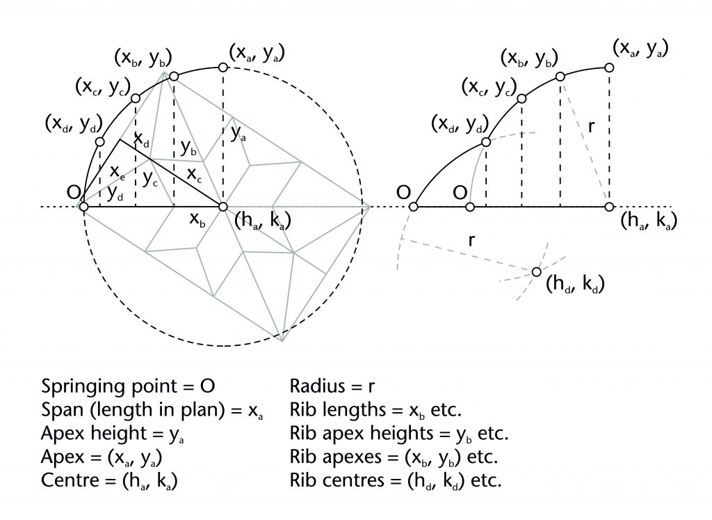
Stieglitz method
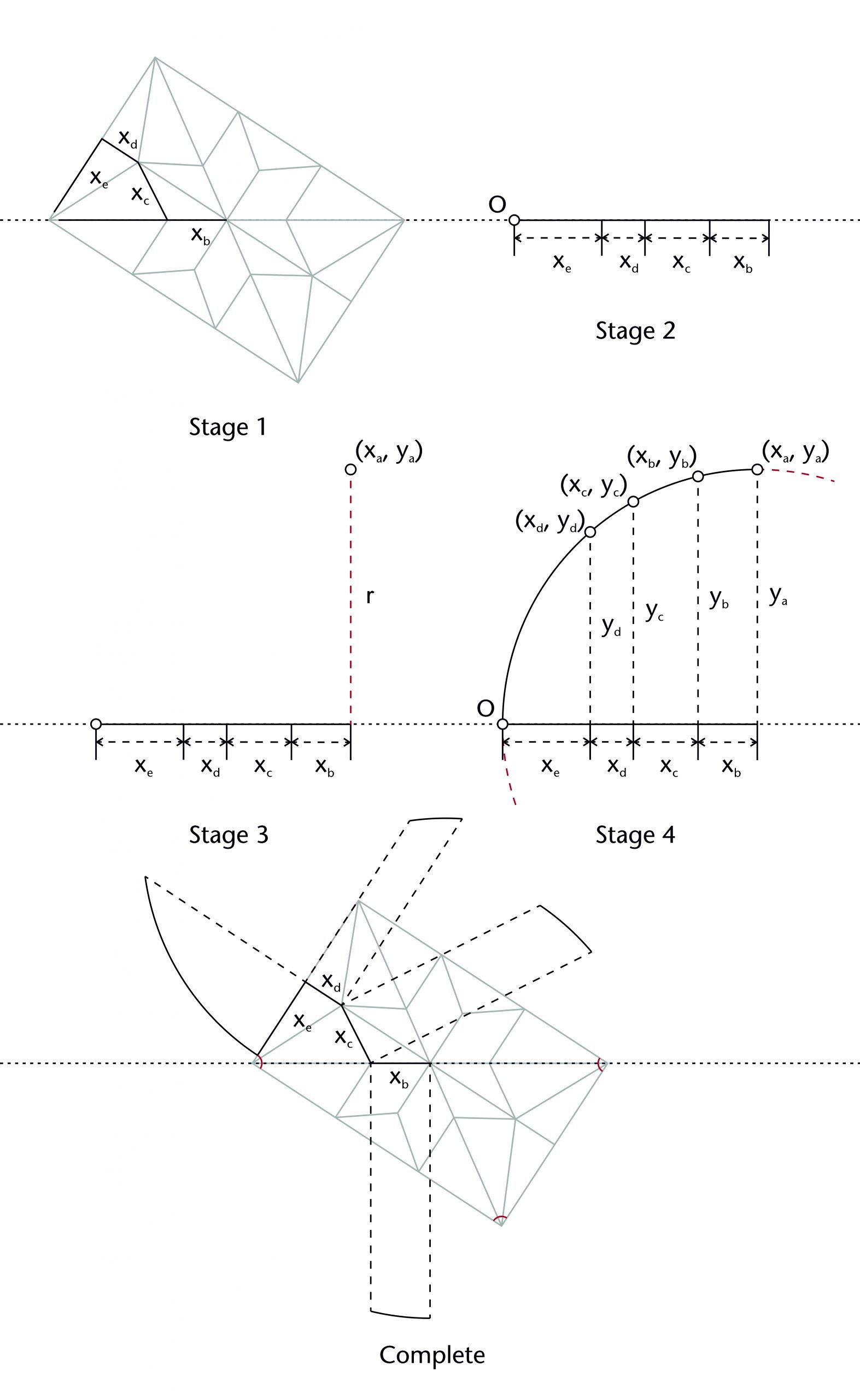
A third Prinzipalbogen method was proposed by the architect Christian Ludwig Stieglitz (1756-1836). The first step was to work out a sequence of ribs of a wandering path leading from the highest to the lowest desired apex for each rib. The spans of each rib (xb, xc, xd, xe etc.) are then arranged into a straight line along the impost, providing the span (xa) and springing point (O) for the principal arch. A circle is then drawn centred on the end point of the principal arch’s horizontal length (xa), its circumference passing through the springing point (O). This produces a semicircular arc with a radius equal to the span (r = xa), providing the curvature for all of the remaining ribs as well as the apex height of the vault (ya = r). A line perpendicular to the impost is drawn from each of the points defined by the spans of the individual ribs (xb, xc, xd etc.), their points of intersection with the principal arch providing the heights for each of their remaining apexes and springing points ((xb, yb), (xc, yc), (xd, yd) etc.). This also defines the curvature for each of the ribs.
Fixed elements
Rib spans (xb, xc, xd etc.)
Principal arch centre (h, k)
Dependent variables
Principal arch springing point (O)
Principal arch span (xa)
Principal arch apex height (ya)
Rib apex heights (yb, yc, yd etc.)
Radius (r)
More information
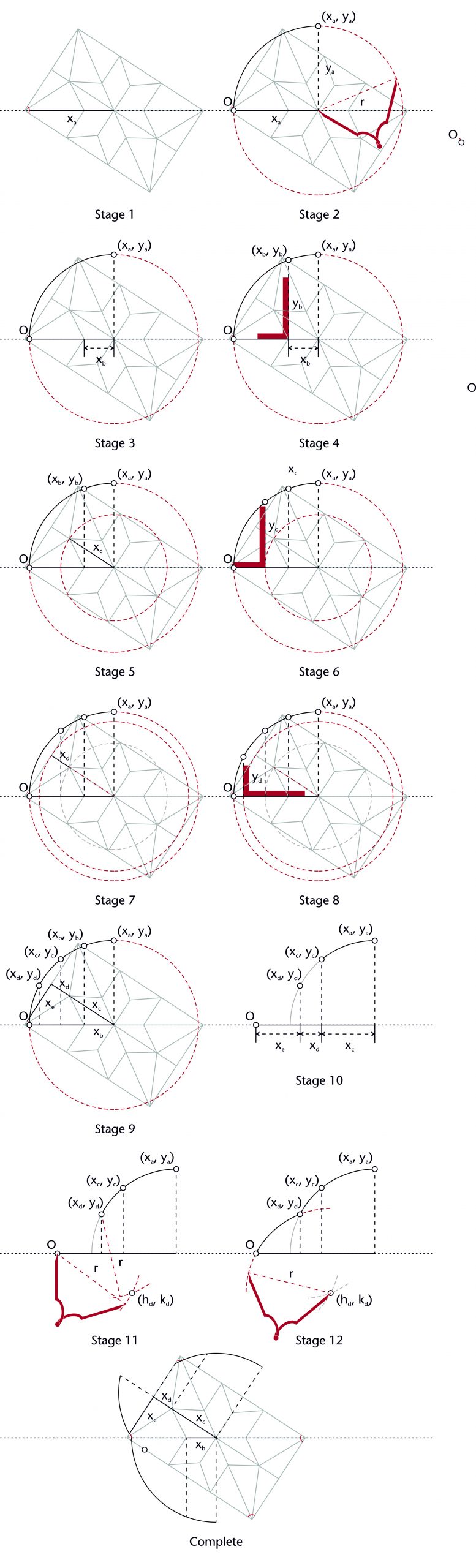
The Stieglitz Prinzipalbogen method can be set out using the following steps:
This method was originally proposed by the architect Christian Ludwig Stieglitz in an unpublished manuscript. Whilst the manuscript does not survive, it was referenced by Friedrich Hoffstadt in his Gothisches ABC-Buch of 1840-63, who provided a detailed description of the process.
Further reading
- Andrés, E. de (2017) ‘The Germ of the Prinzipalbogen Concept in Bartel Ranisch’, Nexus Network Journal 19, pp. 405-25.
- Buchanan, A., Hillson, J. and Webb, N. (2021) Digital Analysis of Vaults in English Medieval Architecture. New York and London: Routledge.
- Bucher, F. (1972) ‘Medieval architectural design methods, 800–1560’, Gesta, 11(2), pp. 37–51.
- Kulig, A. and Romaniak, K. (2008) ‘A Universal Geometrical Method for Reconstruction of Gothic Vaults’, Journal for Geometry and Graphics, 12/1, pp. 81–86.
- Hoffstadt, F. (1840-63) Gothisches ABC-Buch, das ist: Grundregeln des gothischen Styls für Künstler und Werkleute. Frankfurt am Main; Schmerber.
- Muller, W. (1990) Grundlagen gotischer Bautechnik. Ars Sine Scientia Nihil. Berlin: Deutscher Kunstverlag.
- Martín Talaverano, R., Pérez de los Ríos, C. and Senent Domínguez, R. (2012) ‘Late German Gothic Methods of Vault Design and their Relationships with Spanish Ribbed Vaults’, in Carvais, R., Guillerme, A., Nègre, V. and Sakarovitch, J. (ed.) Nuts and Bolts of Construction History, Technology and Society. 3 vols. Paris: Picard, 1, pp. 83-90.
- Tomlow, J. (2009) ‘On Late-Gothic Vault Geometry’, in Nowacki, H. and Lefèvre, W. (ed.) Creating Shipes in Civil and Naval Architecture: A Cross-Disciplinary Comparison. Leiden and Boston: Brill, pp. 193–222.
- Ranisch, B. (1695) Beschreibung Aller Kirchengebäude Der Stadt Dantzig. Dantzig, B. Ranisch.
- Ungewitter, G. (1859-64) Lehrbuch der gotischen Constructionen. Leipzig: Weigel.
- Wendland, D., Alonso, M. and Kobe, A. (2014) ‘The vault with curvilinear ribs in the “Hall of Arms” in the Albrechtsburg Meissen: Studies of the concept, design and construction of a complex late Gothic rib vault’, in Campbell, J., Andrews, W., Bill, N. Draper, K., Fleming, P. and Pan, Y. (ed.) Proceedings of the First Conference of the Construction History Society: Queens’ College Cambridge 11–12 April 2014. Cambridge: Construction History Society, pp. 459–68.

7 Comments
[…] Learn more about the chord method […]
[…] Find out more about designing vault plans Find out more about setting out the curvatures of vault ribs […]
[…] Step-by-step design process for a diagonal rib in the Chapter House at Chester using the chord method […]
[…] were used to construct the ribs. The longitudinal ribs could have been constructed using the chord method, as the apex height was defined at the outset and the centre of the arc was positioned at […]
[…] Find out more about the geometrical methods for setting out ribs Diagram of modules in the parametric model […]
[…] distance were markedly different. The most likely explanation is that they were set out using the three circles method, with the radius (4.62m) perhaps being given by the distance from the floor level to the top of the […]
[…] Find out more about how rib curvatures were set out by medieval designers […]