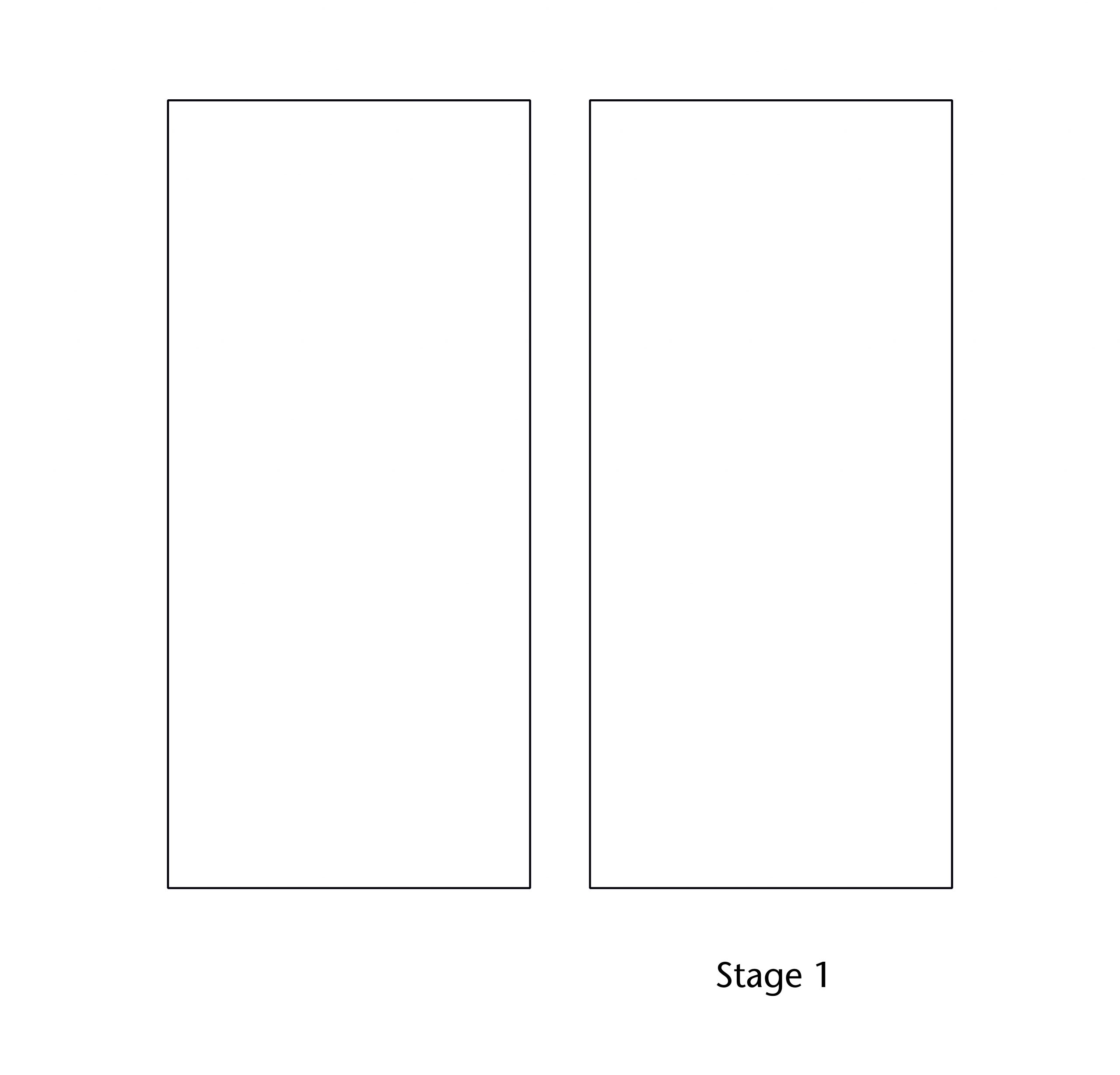
The first stage of design for any medieval vault was to set out its plan. Vault plans were conceived as a two-dimensional pattern of ribs, represented by an intersecting network of intrados lines. The layout of these lines was defined in a series of iterative stages using simple geometrical operations. Whilst the general concept of the plan might be worked out on small scale drawings, its final form would be designed at a 1:1 scale on a large flat surface. Once the dimensions and proportions of the bay had been established, a starting figure would be set out, providing the basic geometrical framework within which the design process would take place. Further lines would then be drawn through the points established by this figure, with each new set of lines provided starting points for further geometrical operations. This method allowed vault plans of great complexity to be devised in a sequence of small, easy steps, each one gradually building up the pattern of ribs.
Measurements and proportions
Before any designer could start work on setting out the vault’s geometry, it was first necessary to define the boundaries of its individual bays. These were usually rectangular in plan, corresponding to the divisions set out during the construction of the building below. Whilst this meant that vault designers were usually dealing with an established set of dimensions, in most cases it is probable that these were set out with a future vault in mind and can therefore be considered an integral part of the design process.
Medieval designers used a variety of different systems for dividing up the plans of their buildings. In some cases a modular system was used, with designers setting out the bays according to defined dimensions. Other designs made use of proportional systems, setting out the length and width of the bays using modular ratios (2:1, 3:2, 4:3 etc.) or simple geometrical operations (1:√2, 1:√3, 1:√4 etc.). This enabled bay plans to be scaled up or down without the need for mathematical calculation. Furthermore, it allowed the different parts of the building to be integrated through shared proportional relationships, as we can see in the repeated use of 6:5 ratios in the east end at Wells Cathedral.
Geometry
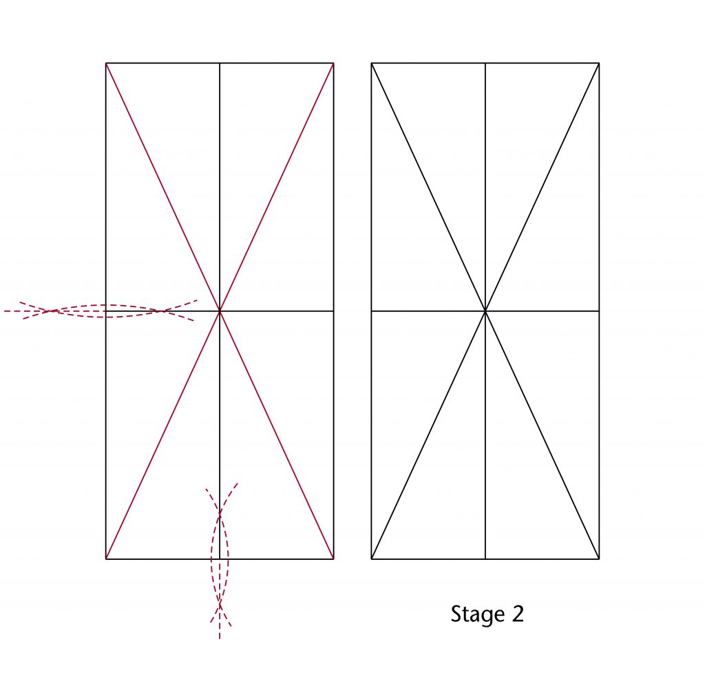
With the dimensions of the bay established, the designer could then move on to laying out the pattern of the ribs. The start and end points for each rib were invariably defined using the geometrical principle of intersecting lines. The first step was usually to define the midpoints of the sides and the centrepoint of the vault plan, allowing the ridge lines and diagonals to be drawn in. With this basic framework in place, the designer could then begin to set out a starting figure. Some ribs would be defined by the figure alone, but others would require the drawing of additional construction lines. Each line drawn provided a new set of points of intersection with its predecessors, expanding the range of possibilities for defining ribs.
The design of the vault plan was therefore dependent on an underlying network of construction lines. The position and orientation of each line was determined using a shared set of geometrical methods, the use of which varied from site-to-site and even vault-to-vault.
Perpendicular bisector
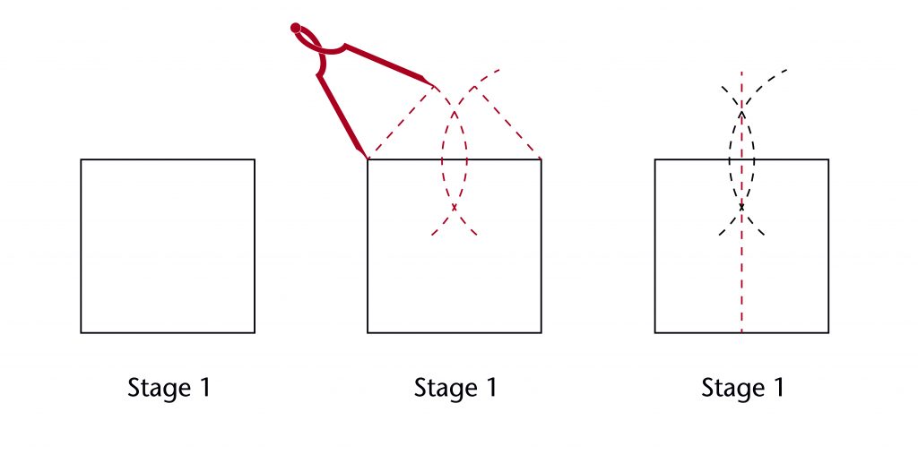
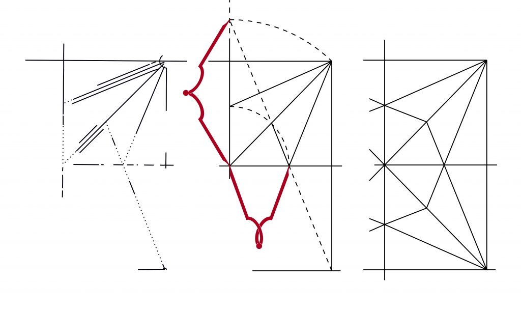
Defining the midpoints of a vault’s sides was an essential part of the design process for any medieval vault. The most accurate method was to use a simple geometrical technique called a perpendicular bisector. Two arcs of the same radius are drawn centred on opposite ends of a line. A second line is drawn through the points of intersection between the two arcs, bisecting the original line into two equal parts. As the resulting bisector is perpendicular to the starting line, it can also be used to divide the plan of the vault into equal parts. This made it extremely useful for laying out bay divisions in medieval drawings, as well as establishing the longitudinal and transverse axes of the vault plan.
Starcut
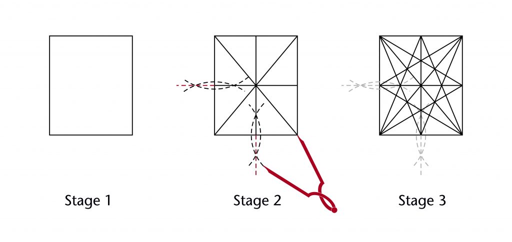
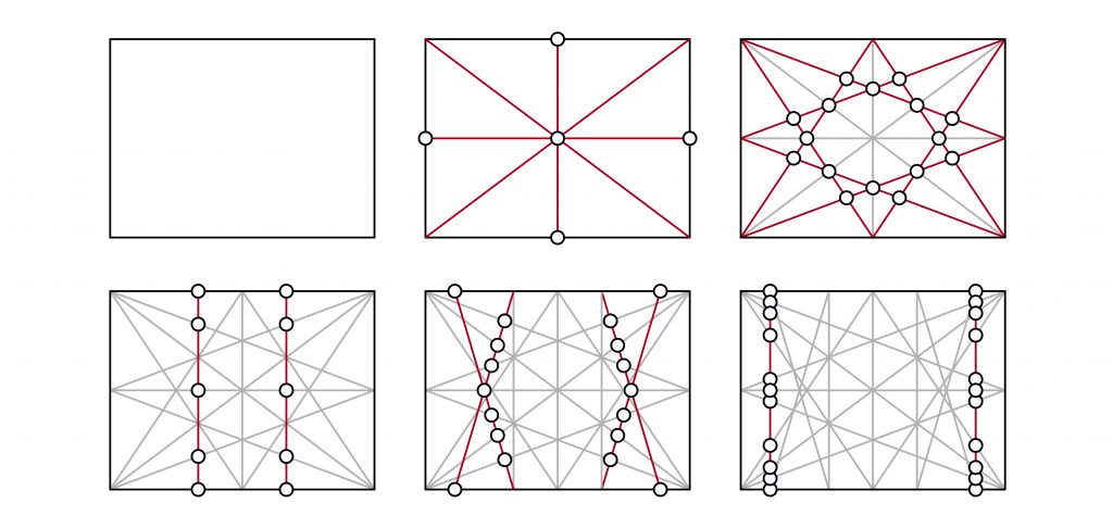
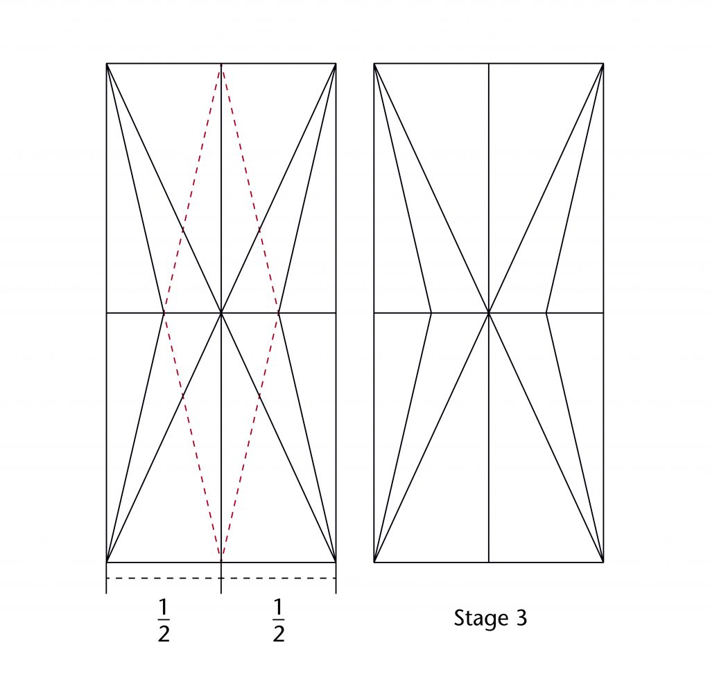
Once the centre of the vault and the ridge lines had been defined, the designer could then draw in their starting figure. One of the most widespread and versatile examples of this which we have identified in medieval vaults is a geometrical figure called a starcut. This figure is defined by connecting the midpoints of each side of a rectangle to its corners, producing a star-like pattern of construction lines. By drawing additional lines through the points of intersection between the lines of the starcut, a designer could divide a vault plan into any number of equal fractions.
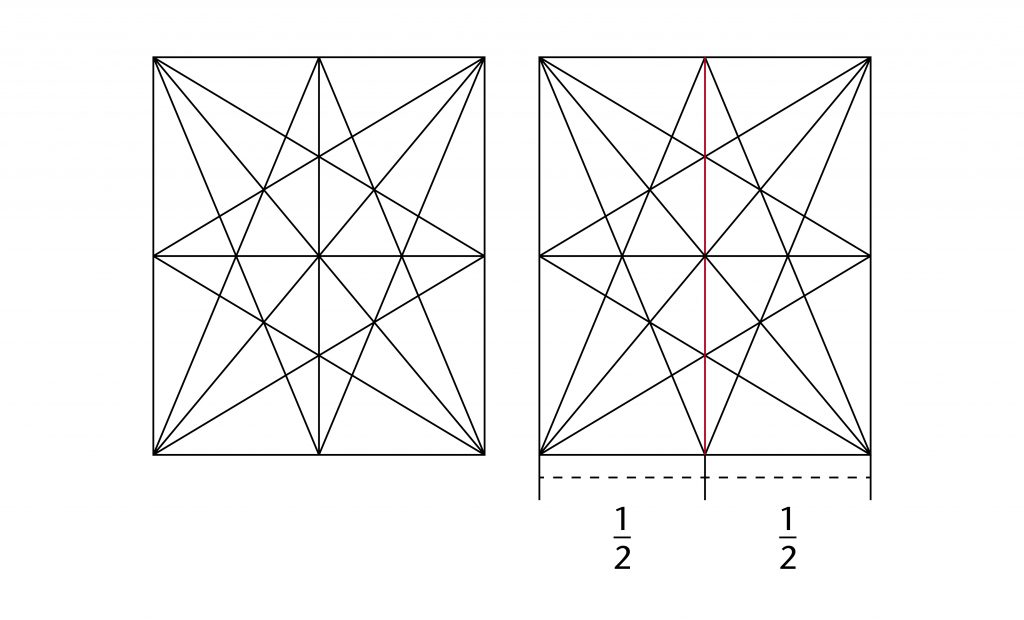
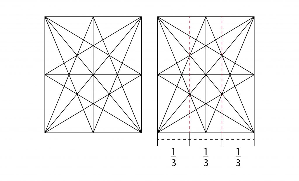
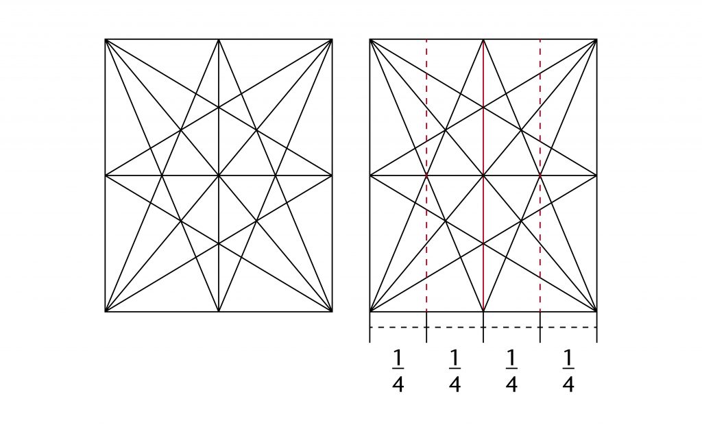
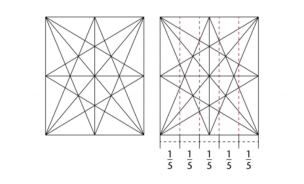
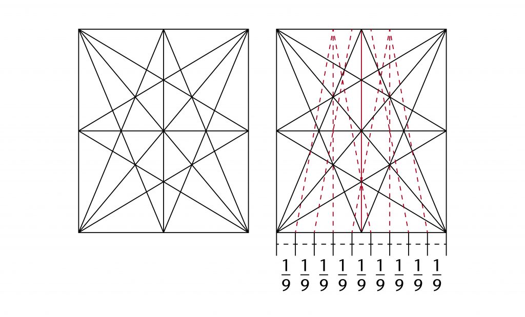
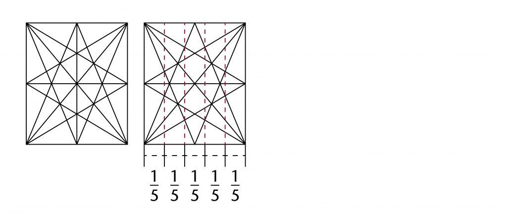
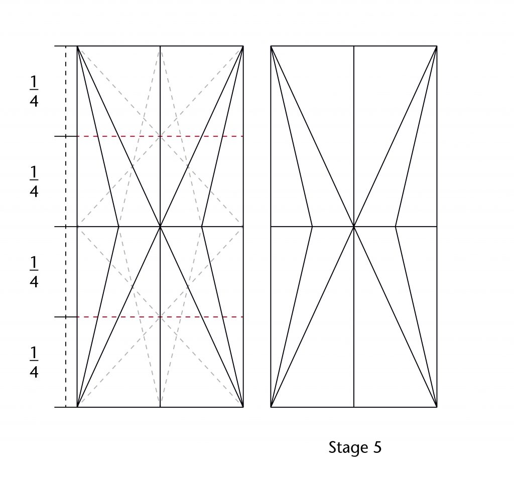
Not only was the starcut itself a useful framework for setting out ribs, but the fractions which it could generate provided endless possibilities for establishing new ribs and construction lines. The most straightforward method was to use the points of intersection on the starcut to define lines perpendicular to the sides of the bay:
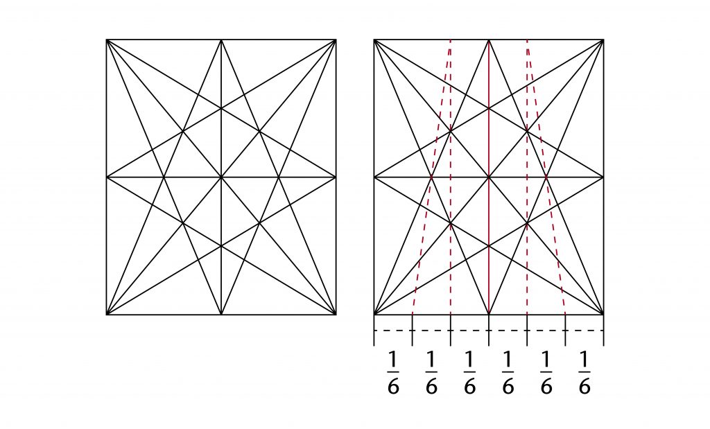
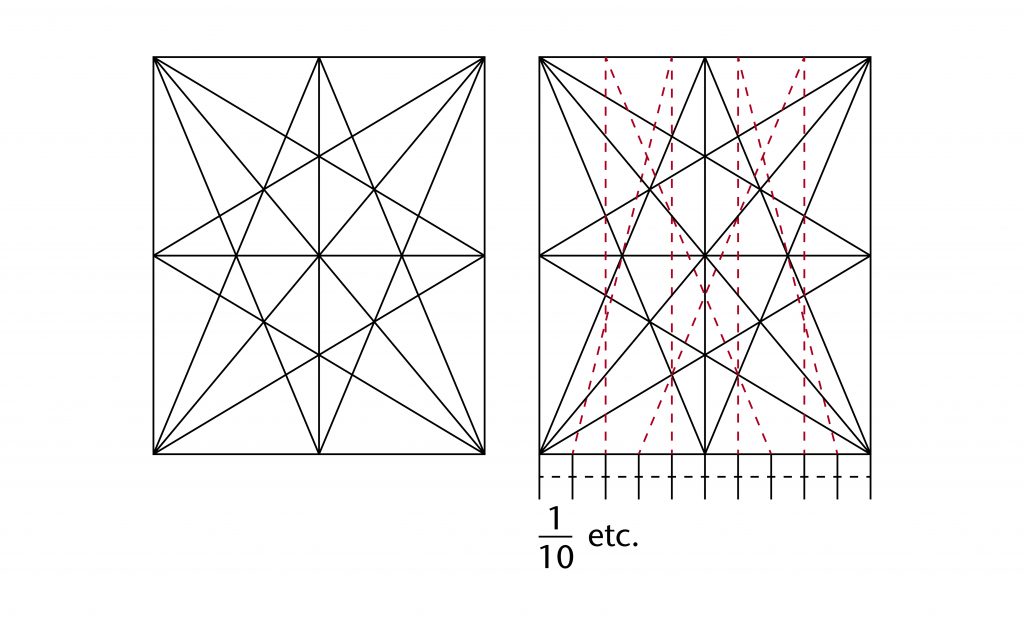
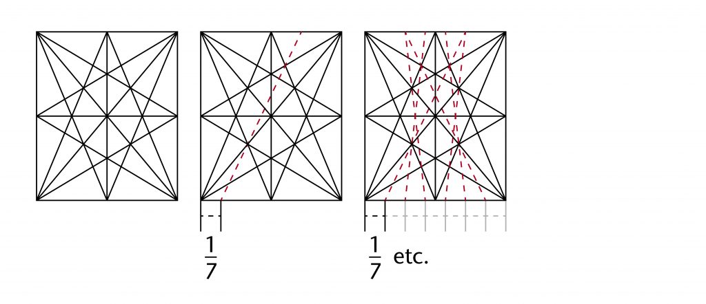
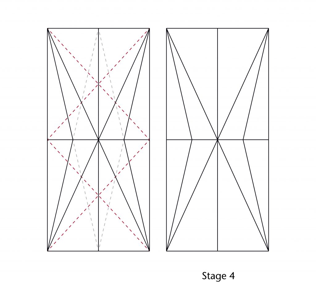
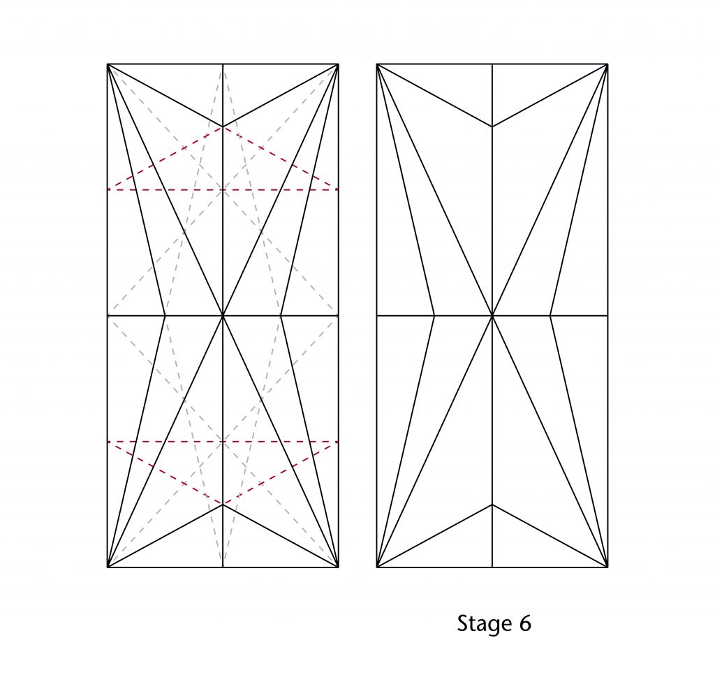
Alternatively, oblique lines could be drawn through two points, their intersections with the outer edge of the bay producing further fractional divisions:
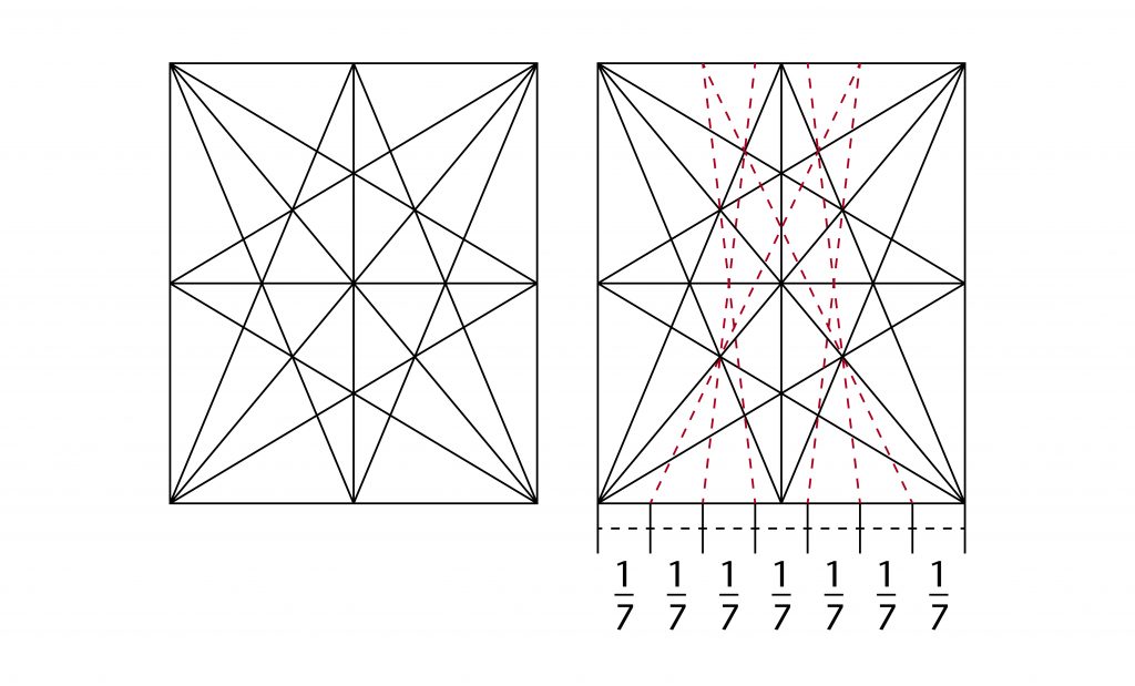
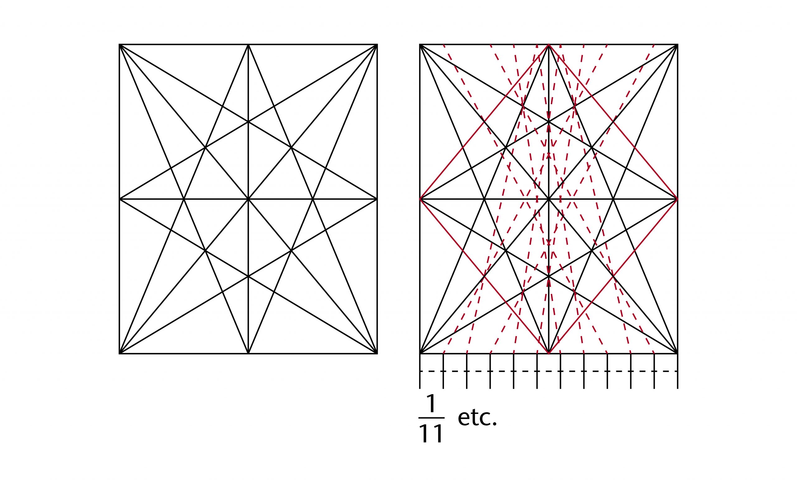
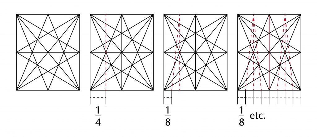
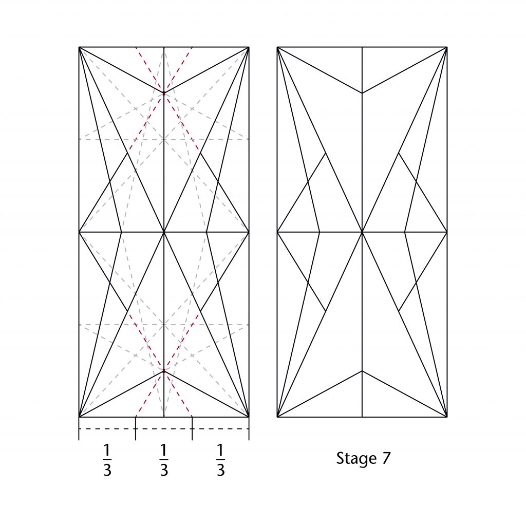
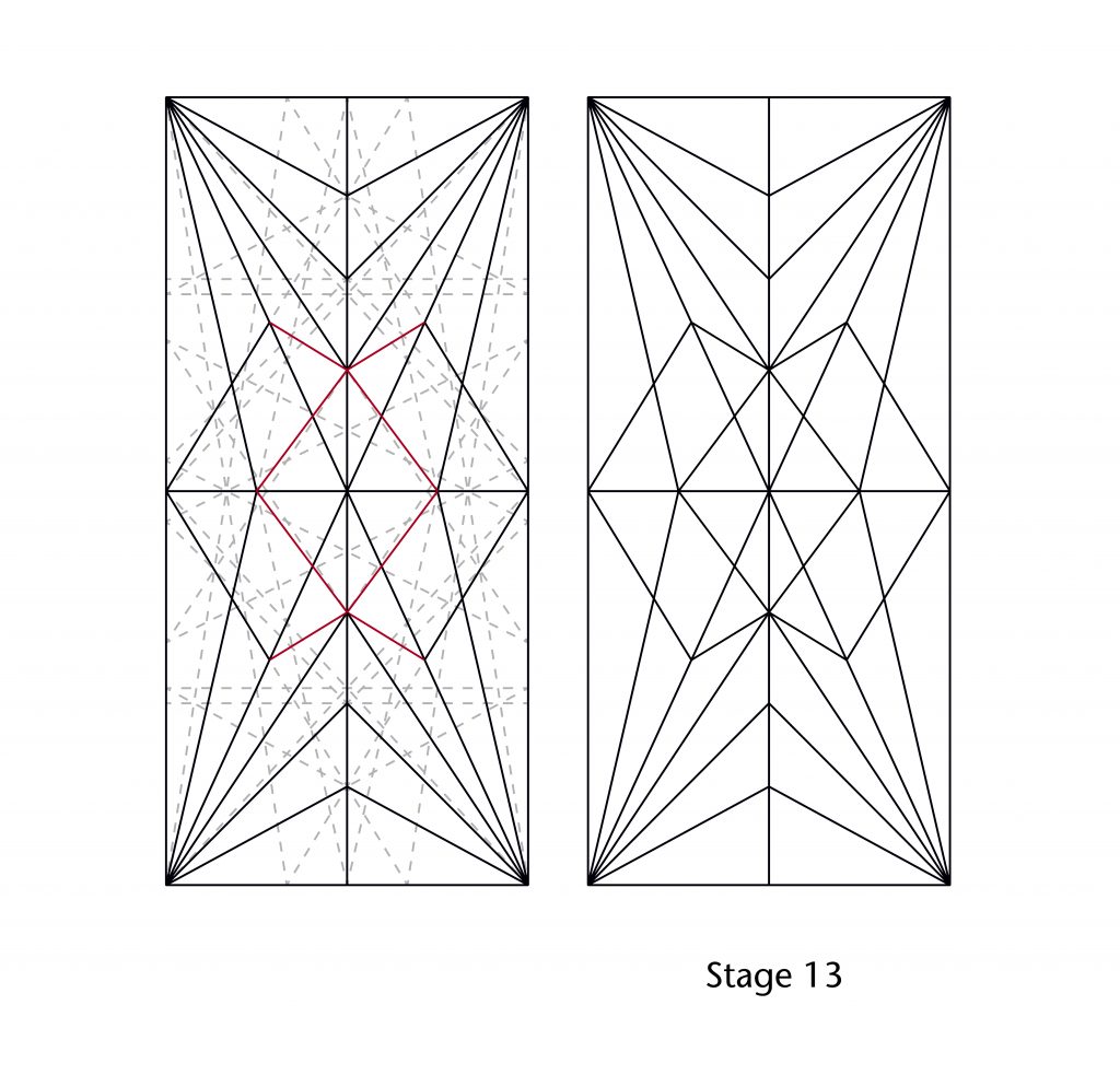
Both of these techniques could also be combined. If a vault was divided using perpendicular lines, the points of intersection between these lines and the sides of bay would provide new starting points for drawing oblique lines. By drawing lines passing through these new points and the existing points of intersection on the starcut, secondary fractional divisions could be produced quickly and easily:
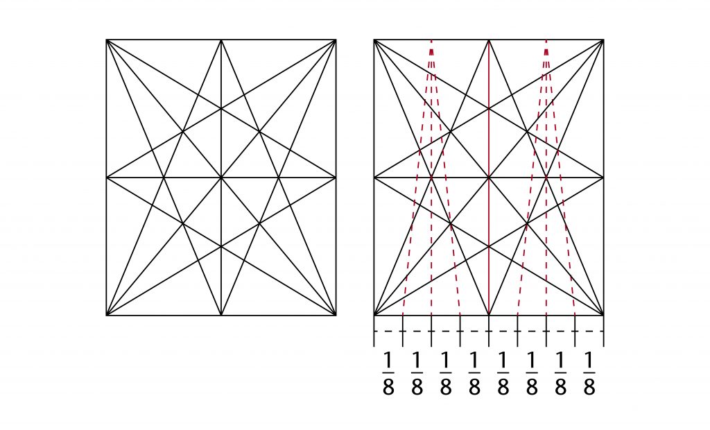
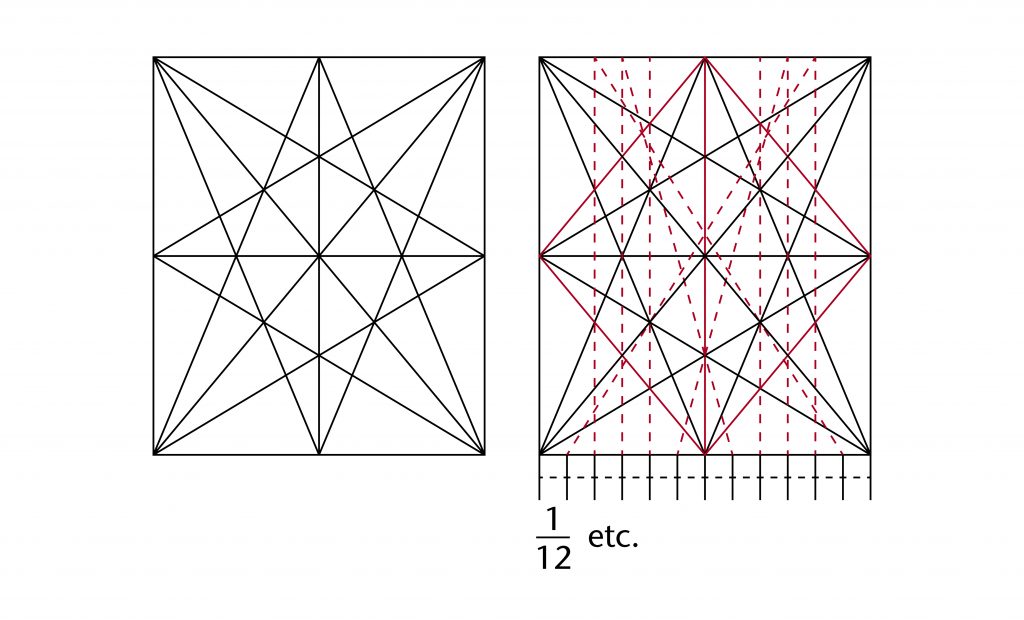
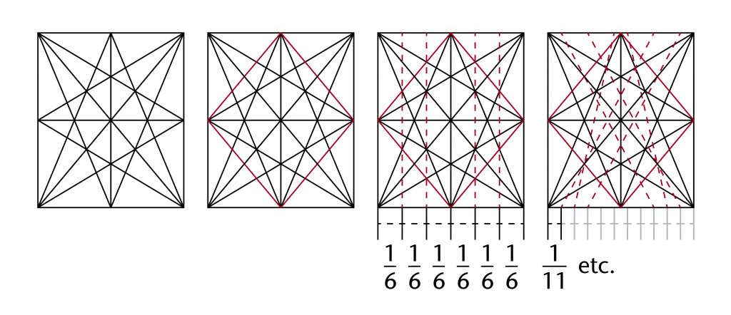
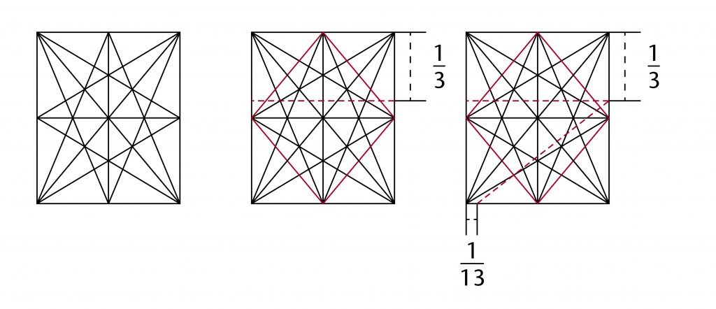
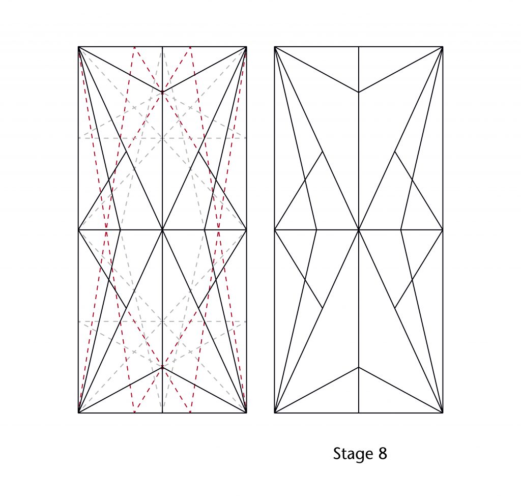
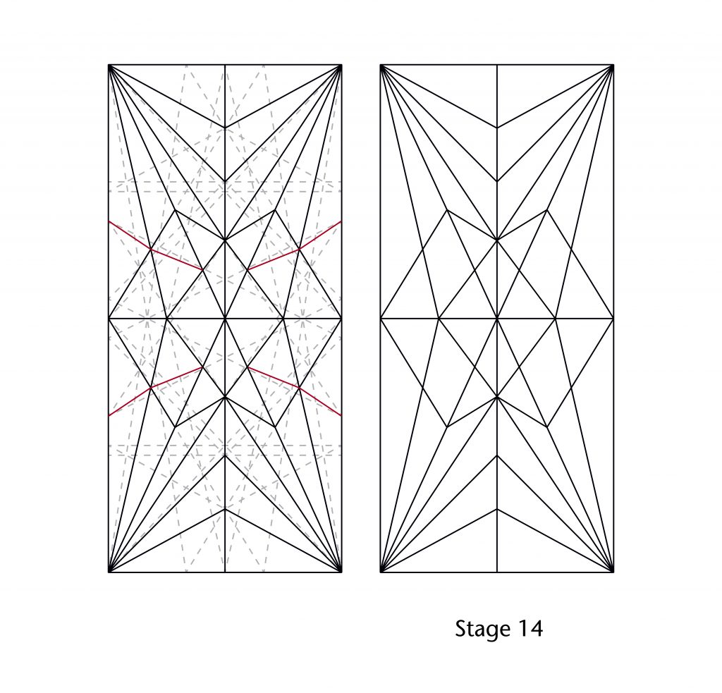
The starcut could be further extended by drawing additional lines connecting the midpoints of each side, forming a rhombus. This provided a new set of points of intersection for drawing proportional divisions, a method which was widely used within our case studies:
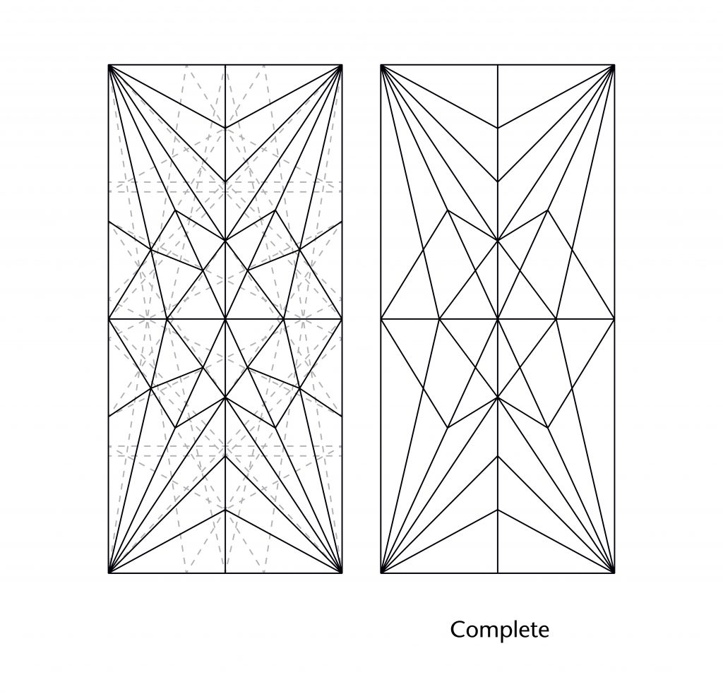
Some proportions could also be set out using lines parallel to the bay sides. This allowed an additional set of starting points to be defined, enabling a wider range of fractions to be set out:
The result was a highly flexible and versatile system for defining the geometry of a vault’s plan, allowing a wide range of design options to be developed within a single linear framework. By using the starcut as a starting figure, a designer would be able to adapt their design quickly and efficiently, testing a variety of different possibilities and easily transferring their forms from bay to bay.
Outer circle starcut
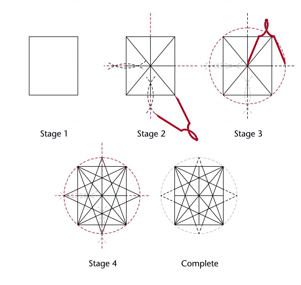
Further variations on the starcut could be introduced by using rotational geometry to expand the outer edges of the starcut beyond the boundaries of the bay. One method by which this could have been accomplished is called the outer circle starcut. This involves drawing a circle passing through all four corners of the bay, centred on the middle of the vault. The intersections between this outer circle and the perpendicular bisectors of the sides of the bay are then connected to the corners of the bay, forming an expanded version of the starcut. The same techniques for dividing up the vault plan using perpendicular and oblique lines can then be used, resulting in a different set of geometrical relationships to those defined by the regular starcut.
Inner circle starcut
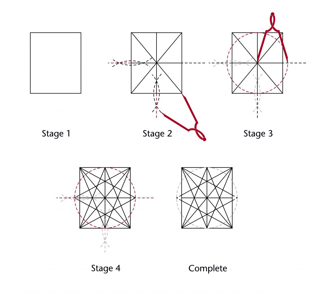
The inner circle starcut is another method for extending the starcut beyond the confines of the bay. It involves drawing a circle with a radius equivalent to the longest side of the bay, centred on the middle of the vault. This results in a starcut where two sides are defined by the midpoints of the shorter sides of the bay, whilst the others are given by the intersections between the inner circle and the perpendicular bisectors of the longer sides. As in the outer circle starcut, the same techniques for dividing up the vault plan can then be used.
Using the starcut
The simplest application of the starcut was to divide the ridge rib of the vault into fractions. This method can be seen in bays C7-C8 of St Hugh’s Choir at Lincoln, where divisions into thirds were used to define the end points of the vault’s tiercerons.
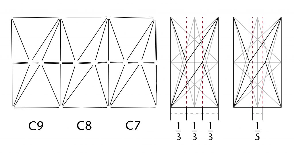
The design could be modulated by changing to a different set of fractional divisions. This can be seen in bay C9 of St Hugh’s Choir, where the tiercerons were instead set out using fifths. The result of this was a far smaller central portion of the ridge rib, rebalancing the proportions of the entire vault. Such adjustments were a frequent aspect of medieval design processes, with slight changes being introduced in order to alter an existing design.
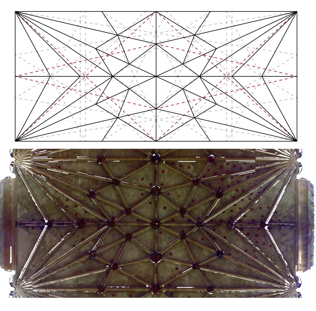
A more complex approach was to combine multiple fractional divisions on both the longitudinal and transverse sides of the bay. This can be seen in bays S7-S9 of the choir aisles at Wells, where divisions into halves, thirds and sixths were used to set out a network of ribs:
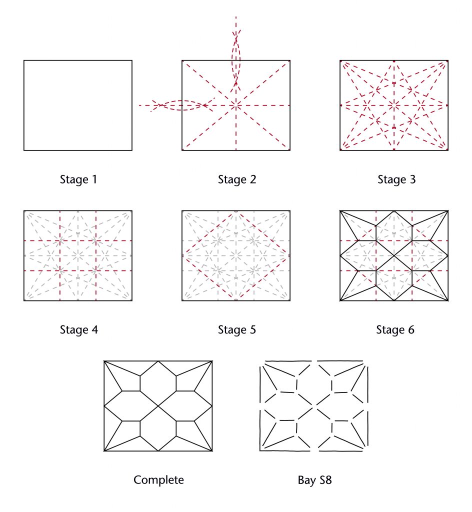
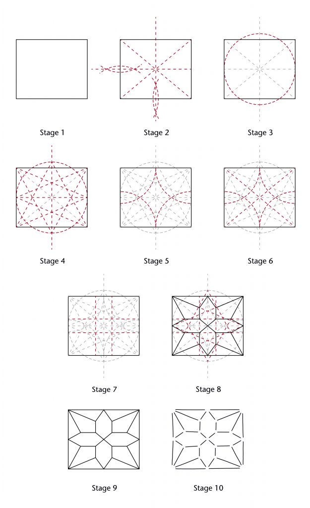
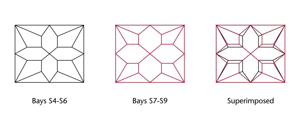
The layout of ribs could also be further modulate by adopting the inner or outer circle starcut. In bays S4-S6 of the choir aisles at Wells, the inner circle starcut was used in combination with other figures. Once the starcut had been set out, four arcs of the same radius as the inner circle were drawn centred on the corners of the vault. The intersection between these arcs and the diagonals of the vault were used to position further lines perpendicular to the sides of the bay. The points where these perpendicular lines crossed each other and the lines of the starcut were used to define the start and end points of the ribs:
Though the resulting vault is very similar in plan to bay S7-S9, detailed observation reveals considerable differences in form. The central cross of liernes is far smaller, resulting in thinner lozenges and a wider angle between the tiercerons springing from the corners.
It was not always necessary to draw out the whole starcut in order to set out a vault. The design for the cloister vault on the tracing floor at Wells Cathedral uses only a partial outer circle starcut, with the majority of the lines being entirely omitted from the geometry.
When the inner or outer circle starcuts are used, the resulting lines no longer correspond to a neat set of fractional divisions. This raises the more general possible that in many cases the fractions found when analysing a vault may be an incidental phenomenon rather than a deliberate design choice. This point can be demonstrated most effectively using the highly complex lierne vaults of Ely Lady Chapel. The vault plan was laid out using halves, thirds, quarters and even thirteenths, the latter using a convoluted series of geometrical operations to define the start and end points of tiercerons and liernes.
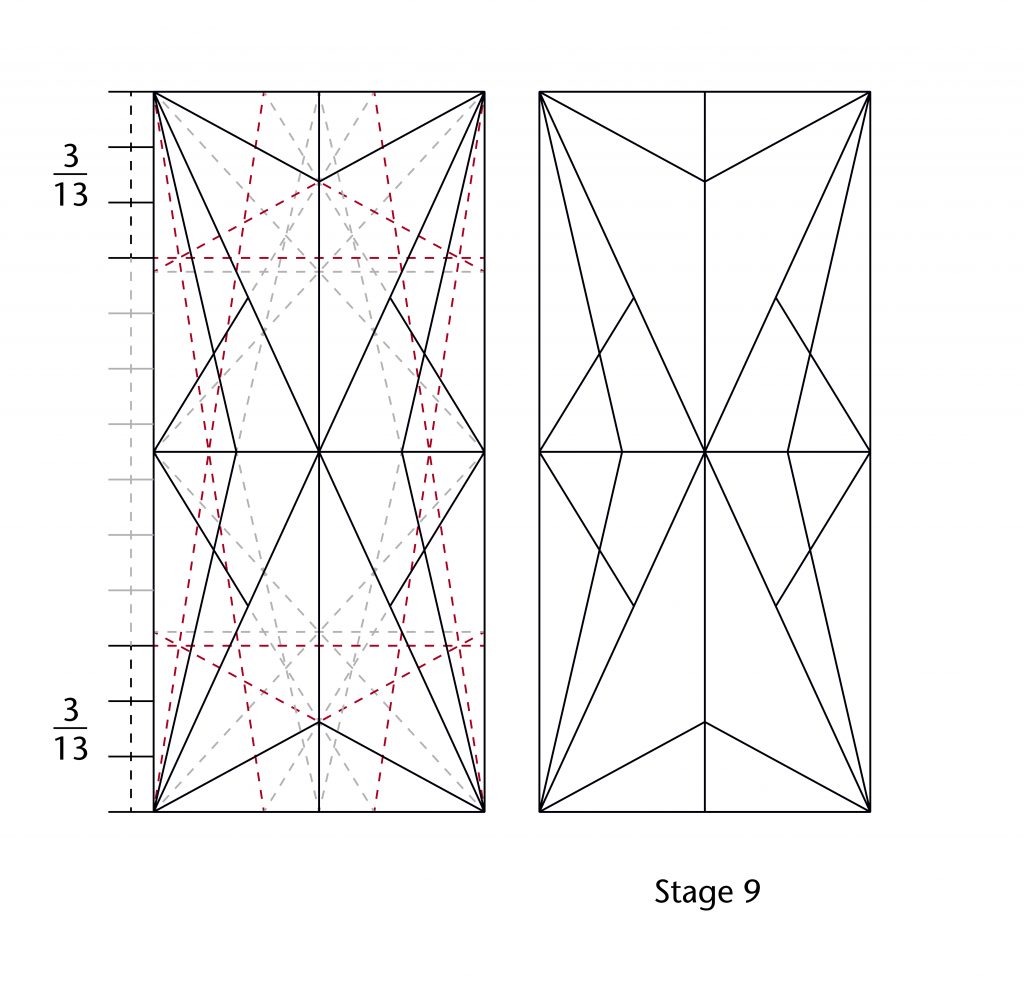
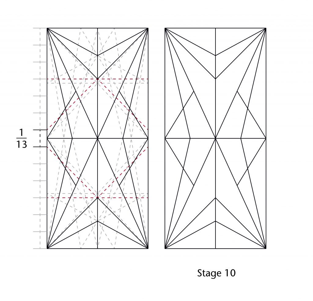
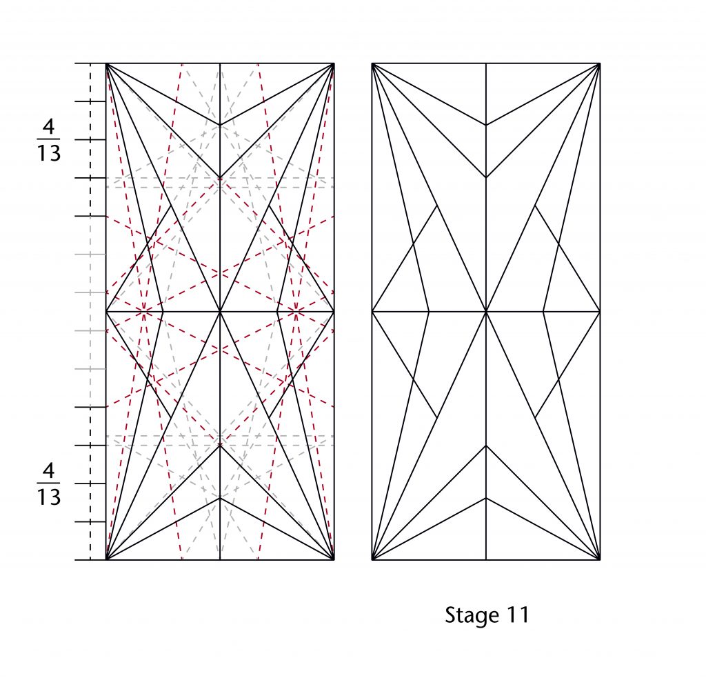
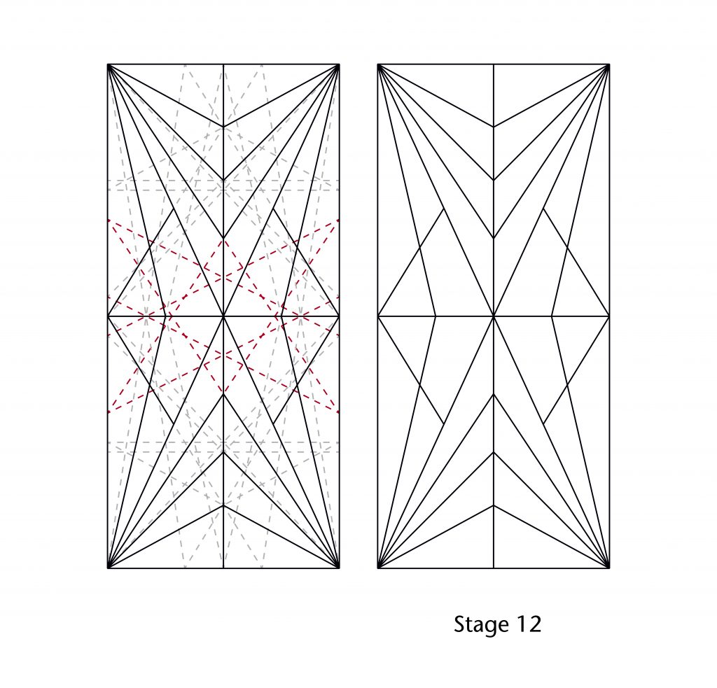
Not only is it unlikely that the use of thirteenths was precisely planned from the outset of the design process, but it is also quite possible that the designer was not even aware of them. The same results could just as easily be created by an iterative process of design through trial and error. Each subsequent line provided a new set of points for further geometrical operations, allowing the vault to be devised freely and dynamically on a step-by-step basis.
Further reading
- Brunés, T. (1967) The Secrets of Ancient Geometry. Copenhagen: Rhodos.
- Buchanan, A., Hillson, J. and Webb, N. (2021) Digital Analysis of Vaults in English Medieval Architecture. New York and London: Routledge.
- Stewart, M. (2009) Patterns of Eternity: Sacred Geometry and the Starcut Diagram. Stourbridge: Floris Books.

4 Comments
[…] Find out more about the history of the site Find out more about out digital surveying methods Find out more about vault design in Hotham’s Choir at Ely Find out more about vault design in Ely Lady Chapel […]
[…] used to set out the vaults at Lincoln, the most likely is some variation on what we have called the starcut. This figure is a highly flexible design tool which can be set out by following a series of simple […]
[…] Find out more about measurements and proportions in medieval vaulting Find out more about the starcut and designing vault plans […]
[…] Find out more about how vault plans were set out by medieval designers […]