When the tracing process for a vault has been completed, the next stage is to produce a series of measurements that allow them to be analysed geometrically. These measurements are taken using Rhinoceros 3D – the same software which we use to trace the vault ribs. In addition to 3D modelling, Rhinoceros includes a variety of analytical tools which we can use to study our wireframe models of rib curvatures , allowing us to measure the apex heights, spans, radii and the centrepoints of their arcs with ease. The resulting values are recorded in extensive tables, providing a comprehensive dataset for studying the geometry of the vaults in each of our case studies.
Identifying and classifying
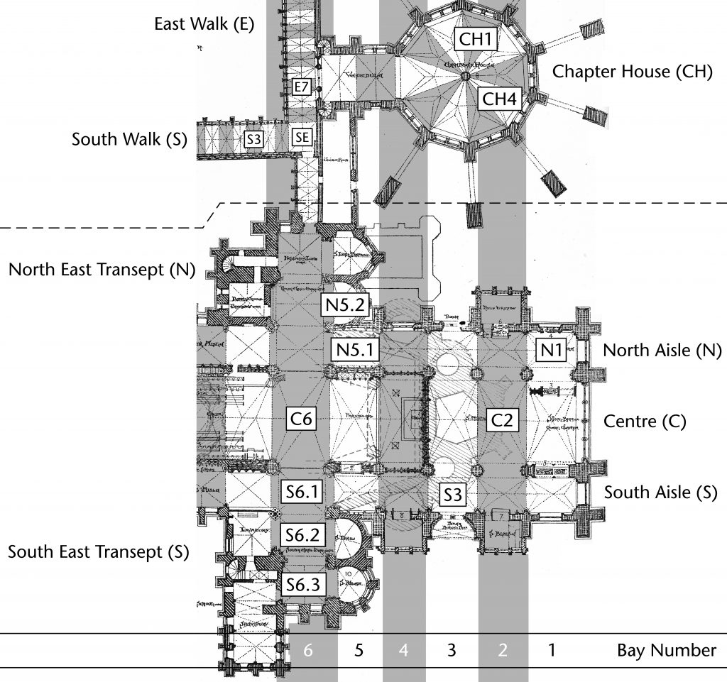
The first hurdle to overcome was how to devise a system which allowed each rib to be identified clearly and unambiguously. Our identification system is divided into two distinct levels. The first is a coordinate-based system for identifying the specific bay in which the rib could be found. In the main body of a church the bays are numbered from east to west, with the central bays being identified by the letter C and the north and south aisles by N and S respectively (e.g. C1, N5, S8). Cloister bays are classified using the north, east, south and west walks (N, E, S, W). The north and south walks are numbered east to west (N1, S5 etc.); the east and west from north to south (E2, W9 etc.). Additional codes are used to identify specific structures such as chapter houses or chapels (e.g. CH1, LC2, MC).
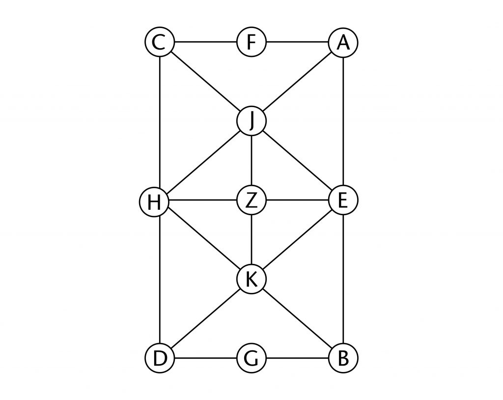
Within each bay the individual ribs is defined using an alphabetical system based on the vault’s plan. For each vault the position of each springing point and apex is given a specific letter. A, B, C and D are used for the corners of the bay, E, F,G and H for the midpoints of the sides, Z for the centre of the vault and the remaining letters are distributed as necessary following a logical pattern. Each rib is therefore identified by a two-letter code corresponding to its start and end point in plan (e.g. AZ, CF, BJ, KN).
Taking measurements
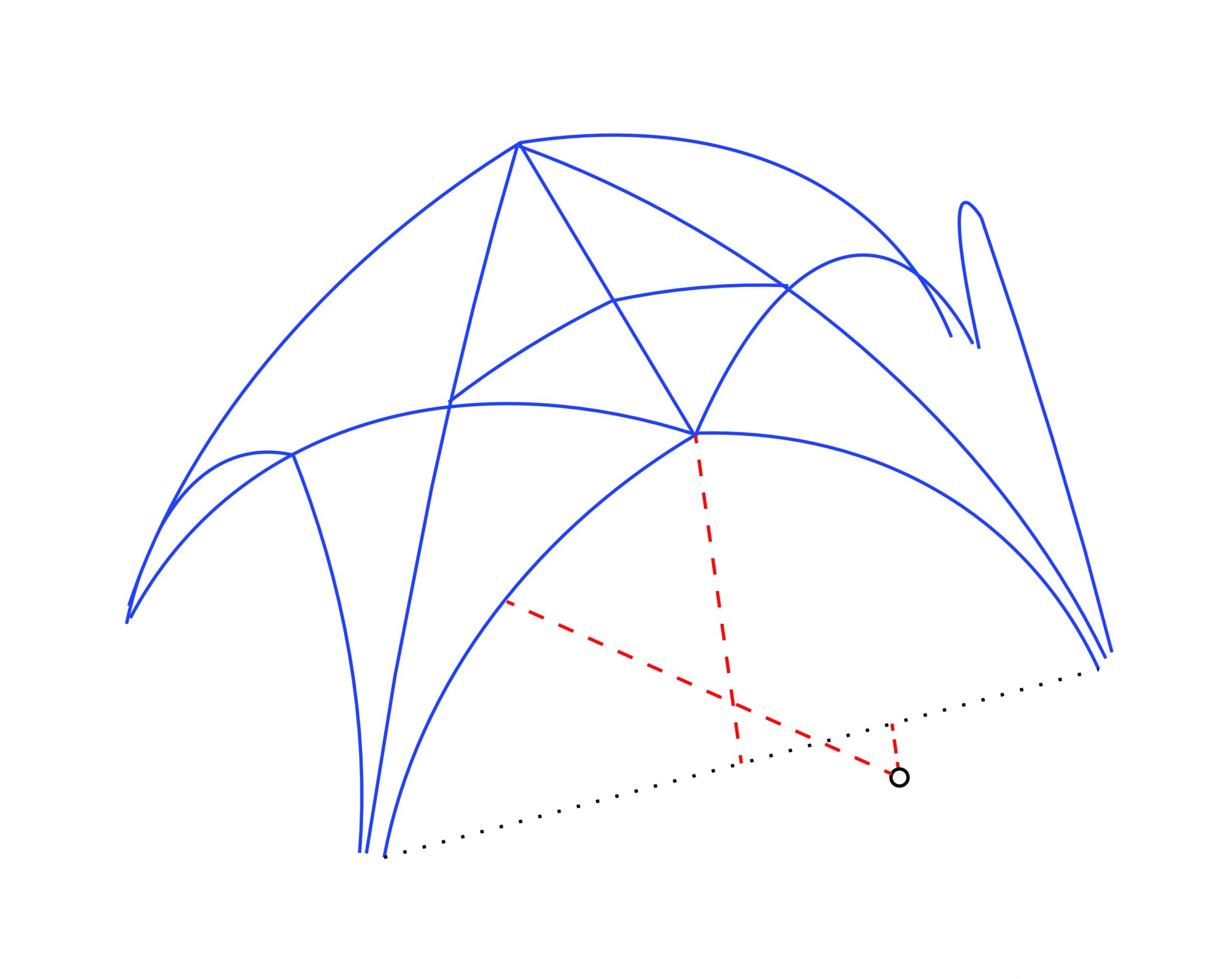
Once the classification system had been worked out, the next issue was to decide on which variables to measure in order to analyse the vault’s geometry. The form of each rib was determined by a set of mutually interdependent variables, with any change in one having a direct effect on the values of the others. Every rib has a springing point (O), a span (xa) and a notional apex or end point (xa, ya) and those with curved intrados lines also possess at least one radius (r) and centre (h, k). By fixing some of these variables in advance, medieval designers were able to define the remaining elements by selecting an appropriate geometrical method. Through measuring some of these variables, it is therefore possible to suggest which geometrical techniques could have been used by the designers in setting out their ribs.
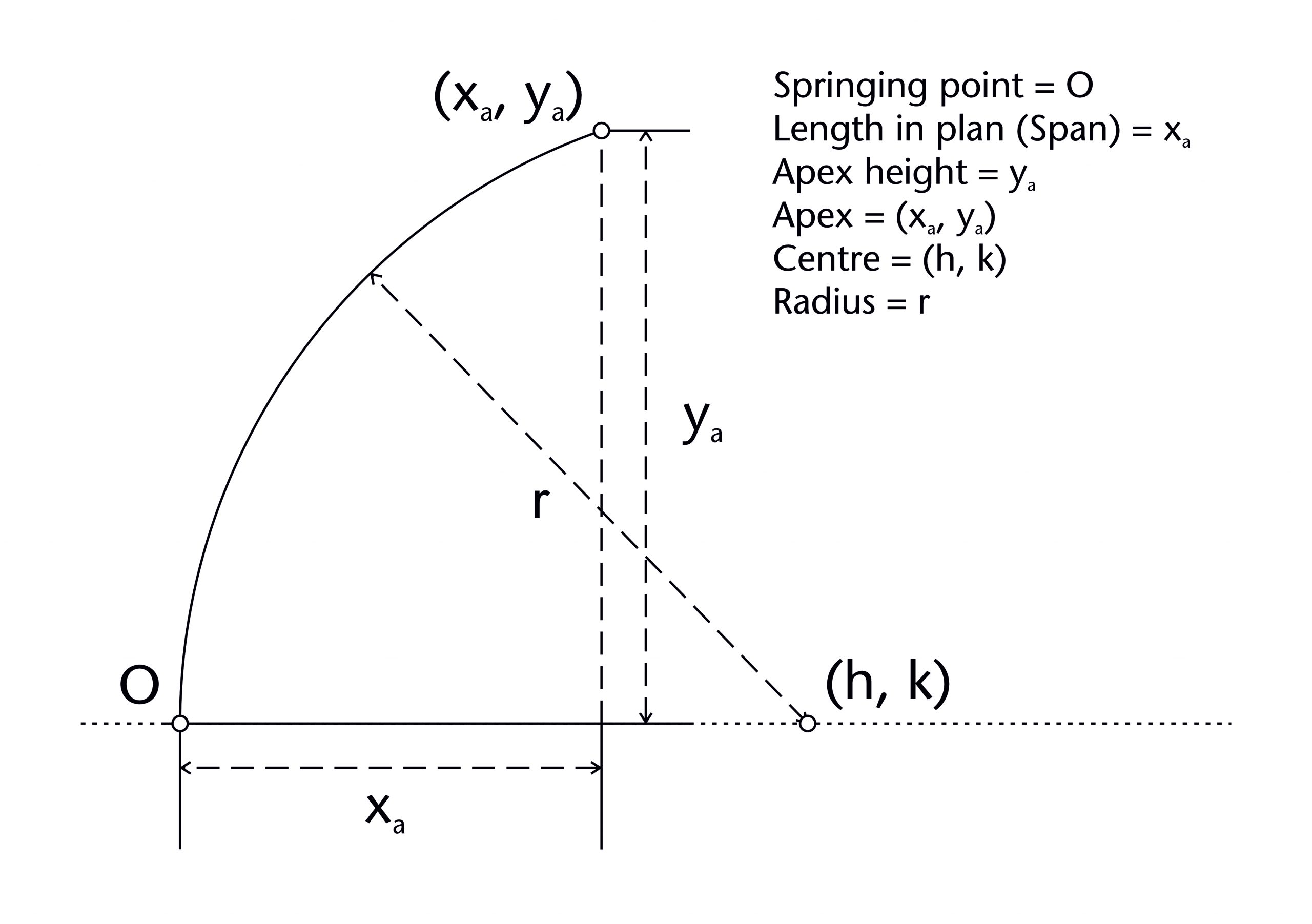
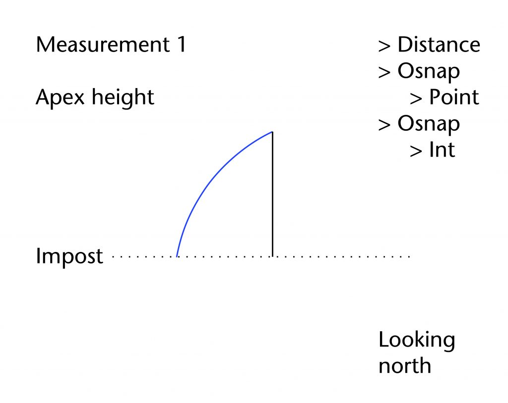
The first measurement which we selected is the apex height relative to the impost level (ya). This provides a vertical position for the apex of the rib, allowing us to determine whether or not this could have been a fixed element at the outset. It is measured from the notional apex of the best fit arc, a theoretical point which was usually covered by a protruding sculpted boss.
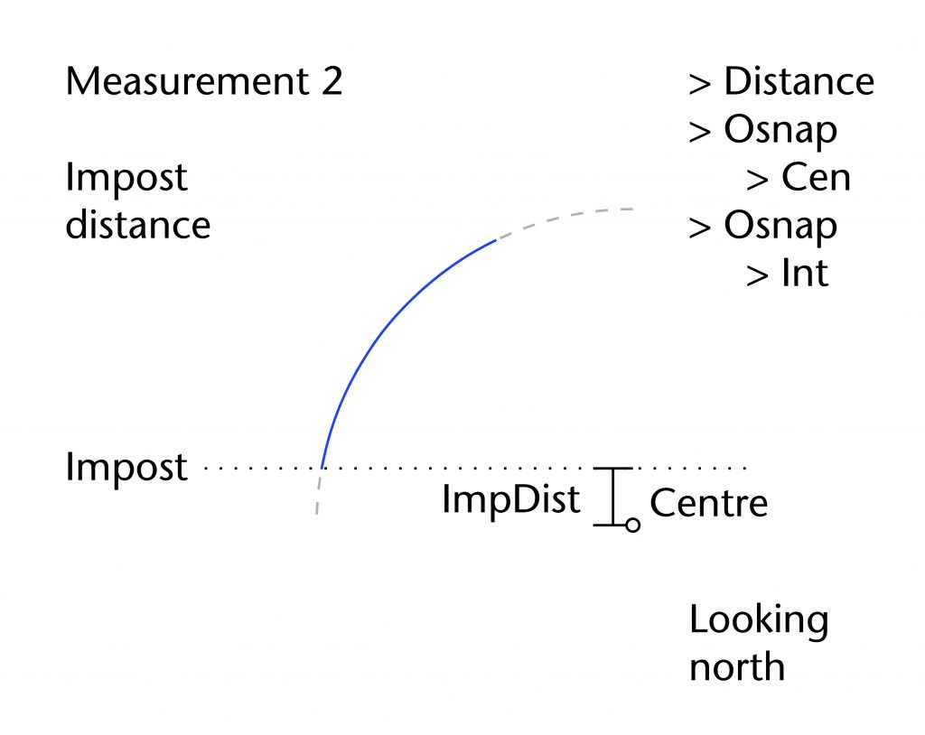
The second measurement is the vertical distance from the impost level to the centre of the best fit arc (k). This enables us to assess whether or not the centre was located at the level of the impost (k = 0), potentially showing that the height of the centre was defined in advance.
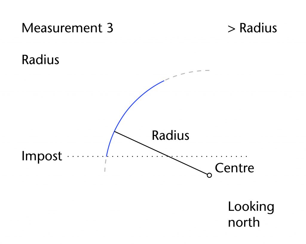
The third and final measurement is the radius of the best fit arc (r). This enables us to consider whether or not the radius was identical from one type of ribs to another, allowing us to hypothesis whether or not the designers made use of a fixed radius throughout the vault.
Each of these measurements is recorded to the nearest millimetre and tabulated using Microsoft Excel. The results are organised using the identification system outlined above, starting with the different sections of the building (choir, nave, south nave aisle etc.). Within each section, each bay (C7, C9, C10 etc.) is given its own table. Measurements are recorded on a rib-by-rib basis, with the specific reference code (AF, BG, DP etc.) being used to group the radius, impost distance and apex height of each individual rib. This provides a complete, navigable dataset for each of our case study sites, allowing us to develop our hypotheses regarding their design process on a rib-by-rib basis.
Further reading
- Buchanan, A., Hillson, J. and Webb, N., Digital Analysis of Vaults in English Medieval Architecture. New York and London: Routledge, 2021.
2 Comments
[…] Find out more about our measurements Find out more about our 3D mesh models […]
[…] Find out more about the measurements which we take and how they are recorded […]