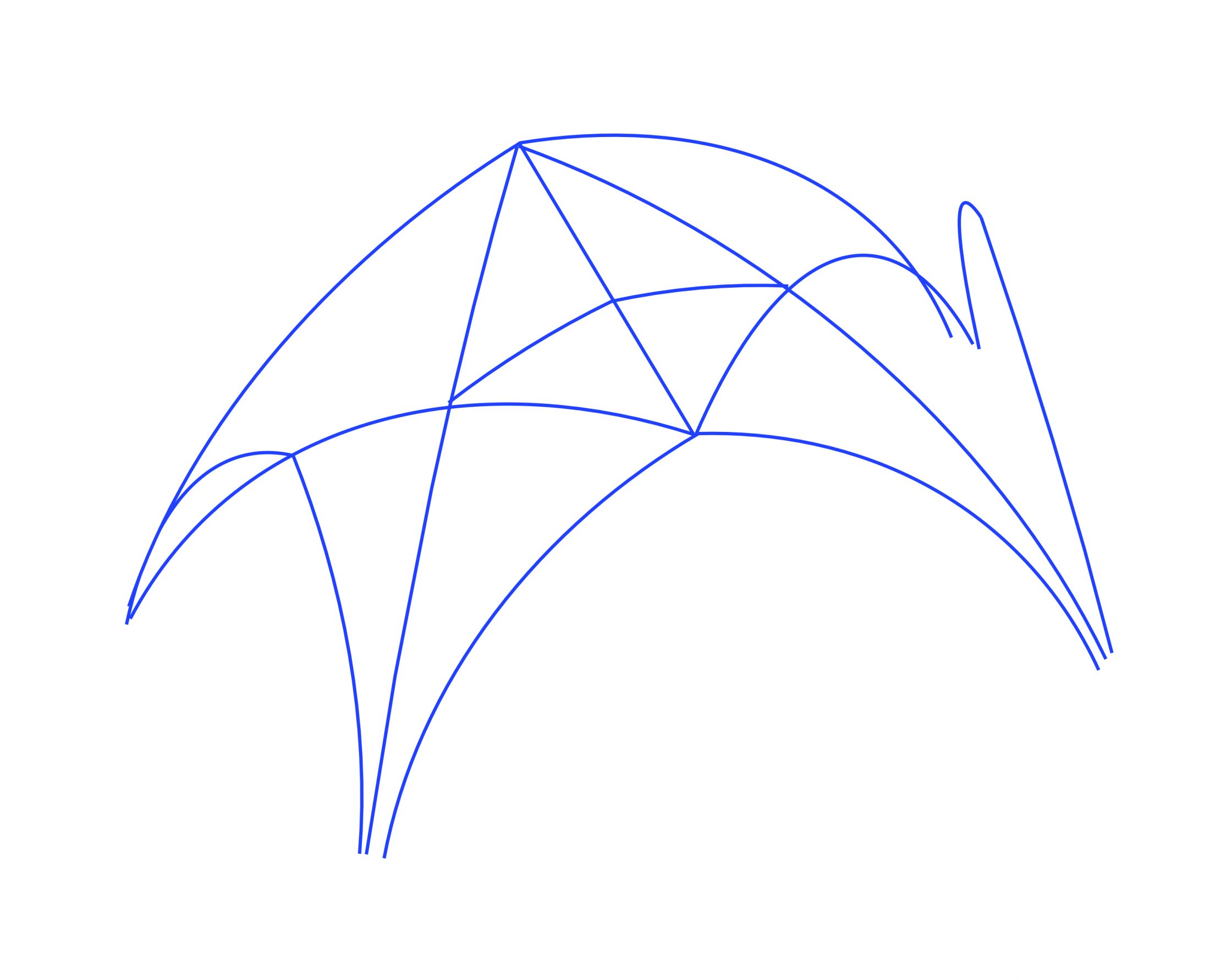
Once the laser scanning data has been recorded and processed into 3D mesh models, the next step in our research process is to retrace the intrados lines of the ribs. This is accomplished digitally using Rhinoceros 3D, a specialist 3D modelling platform. Rhinoceros includes a variety of different tools for drawing three-dimensional geometry, including several for taking sections of 3D models automatically. By using these functions on each of the ribs within our mesh models, it is possible to produce a wireframe model of their curvatures, providing the basic framework within which all of our measurements can be taken.
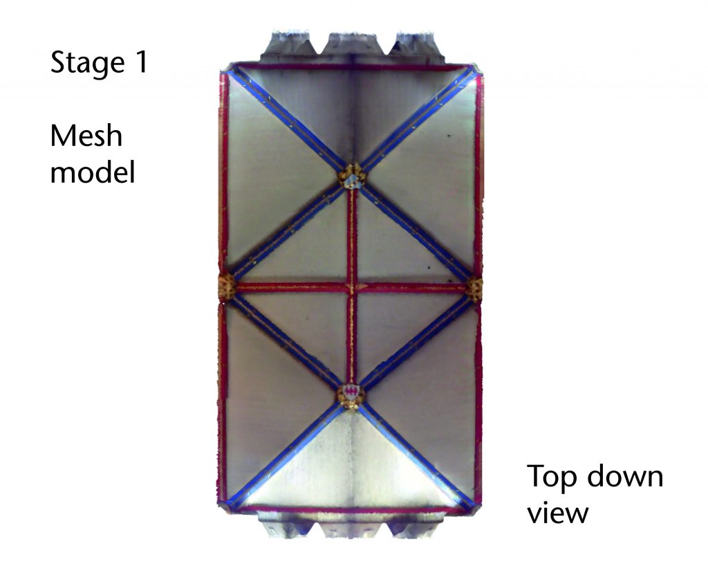
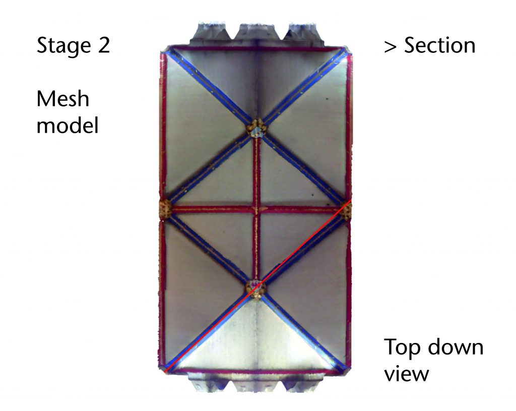
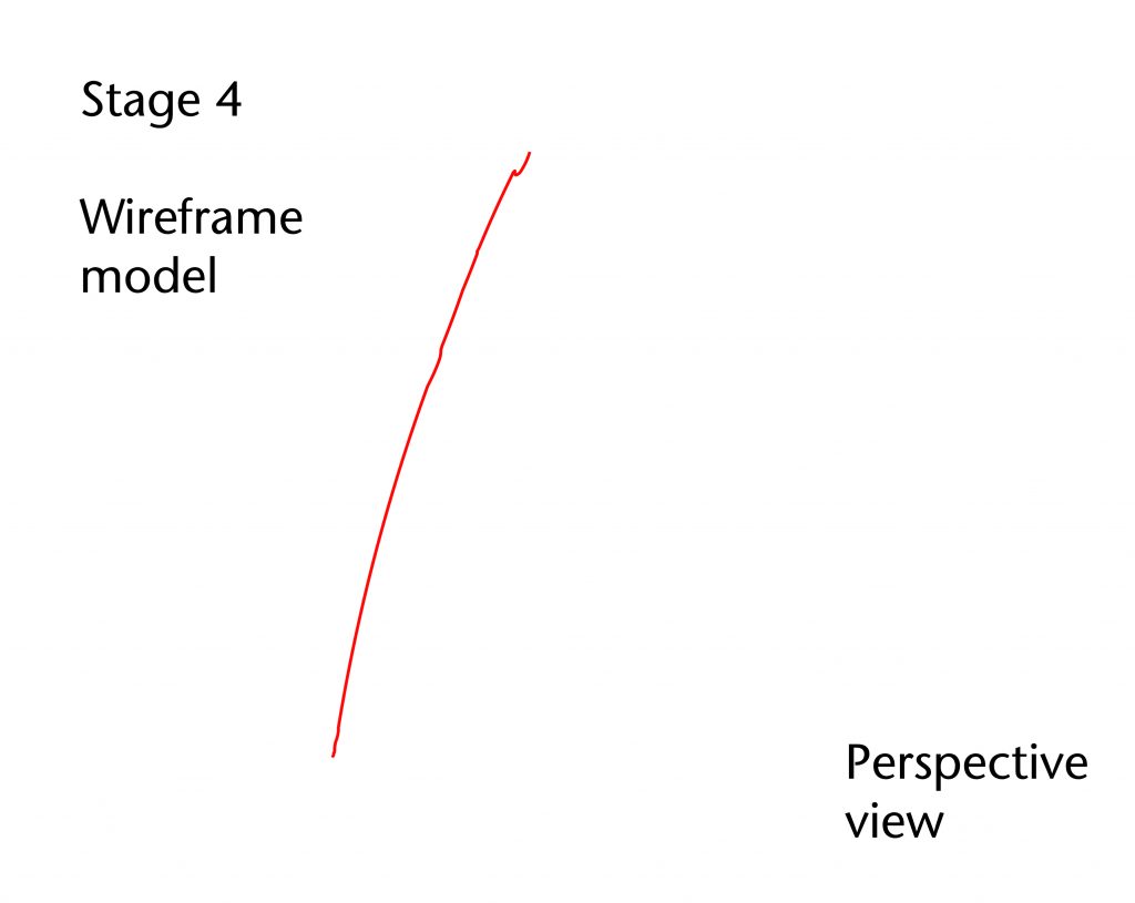
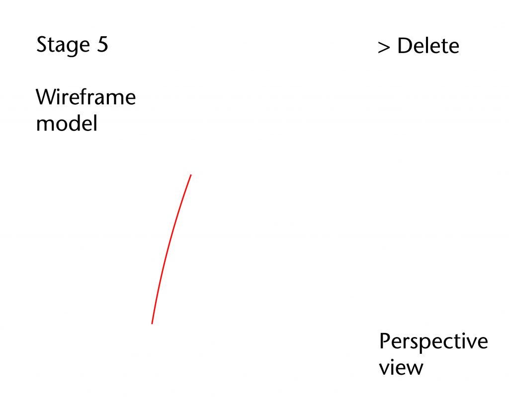
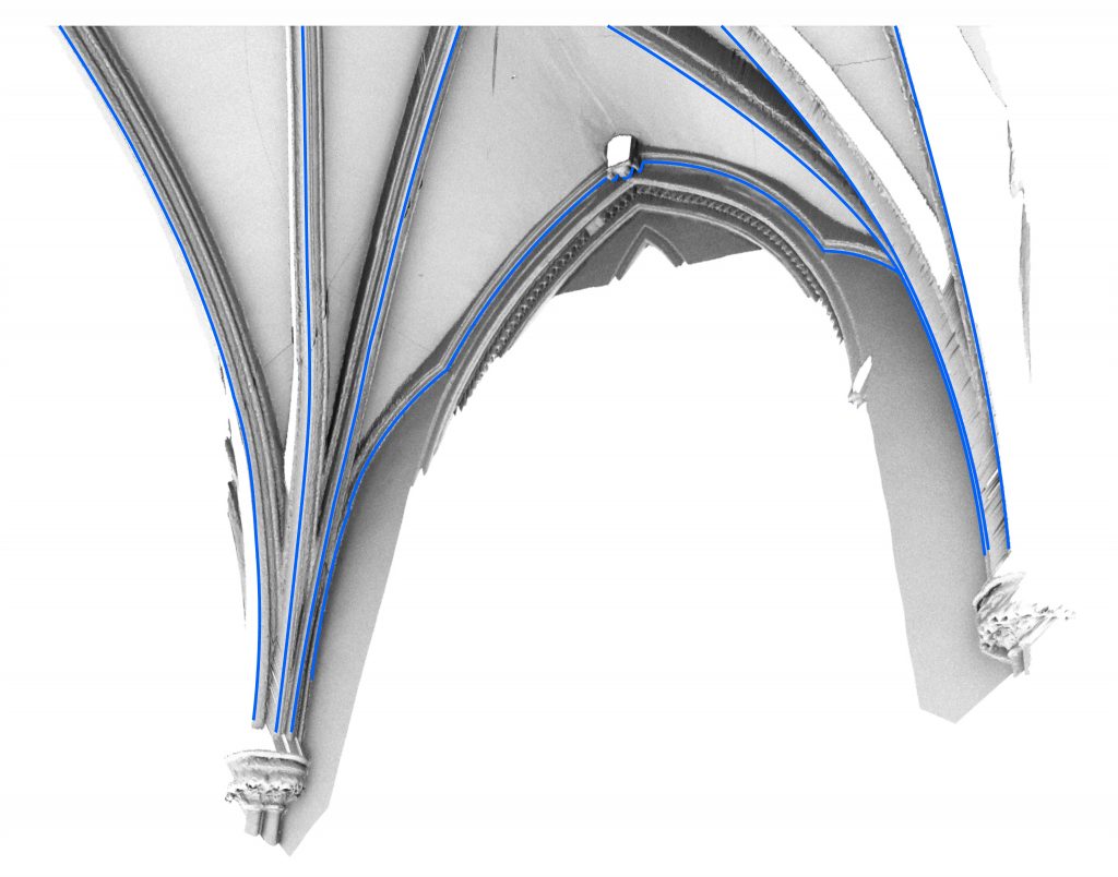
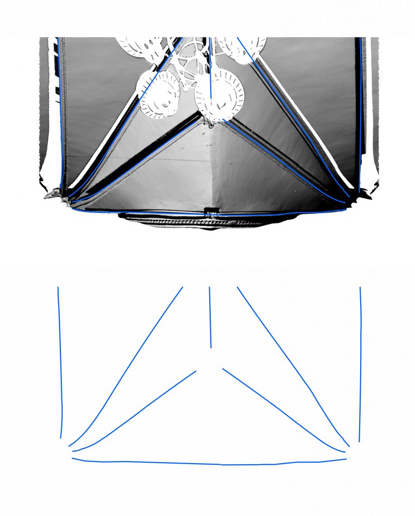
The mesh models are imported into the software at full scale and displayed in top view, providing an accurate visualisation of the vault’s plan. The ‘section’ command is then used to draw a line along the apparent intrados of one of the ribs, which is automatically converted into a section cut through the model. This results in a polyline consisting of a collection of points, each marking the intersections between the mesh model and the sectioning line. The traced polyline can then be viewed in perspective and checked for accuracy. Any extraneous points are removed using the ‘delete’ command, leaving only an intrados line following the curvature of the rib.
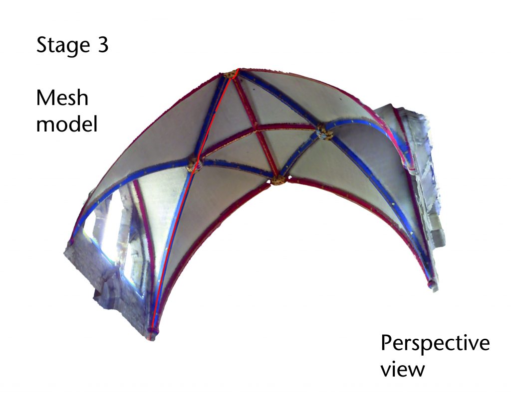
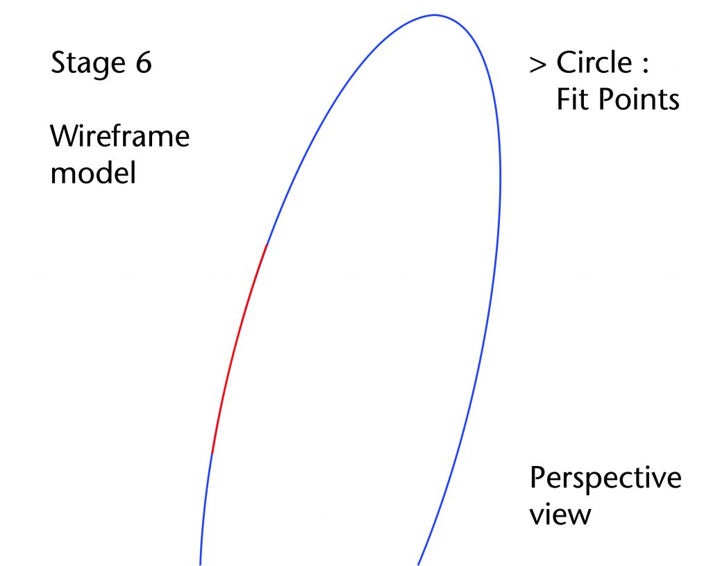
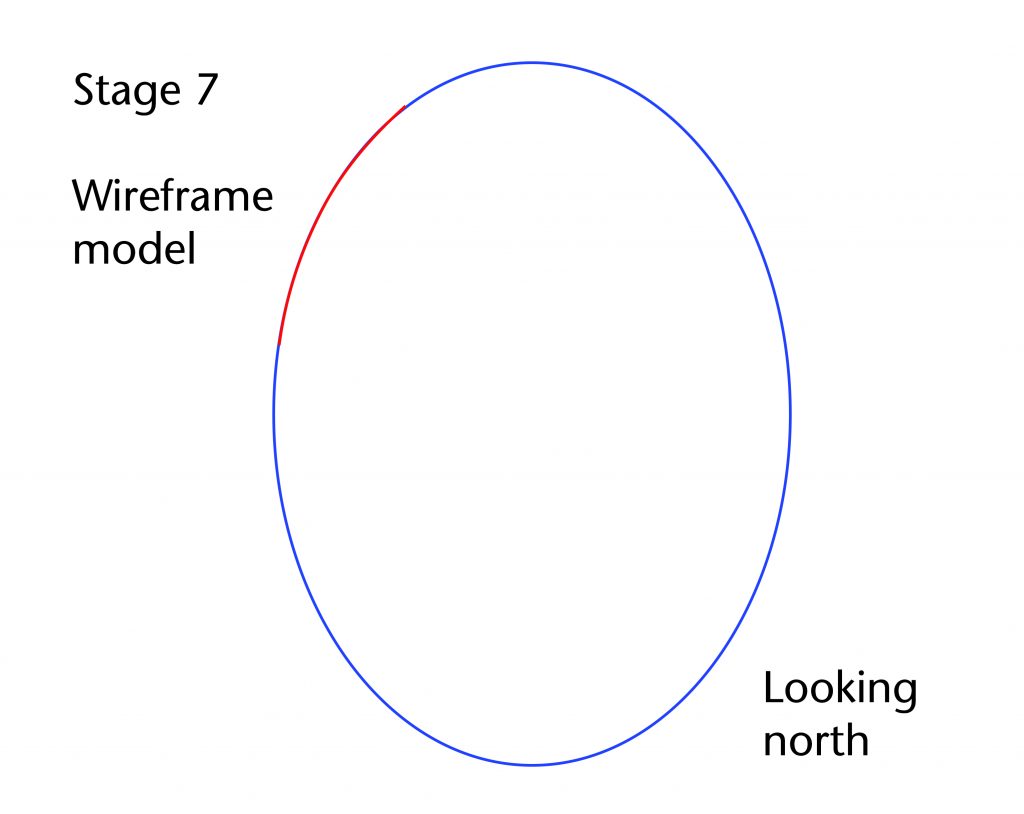
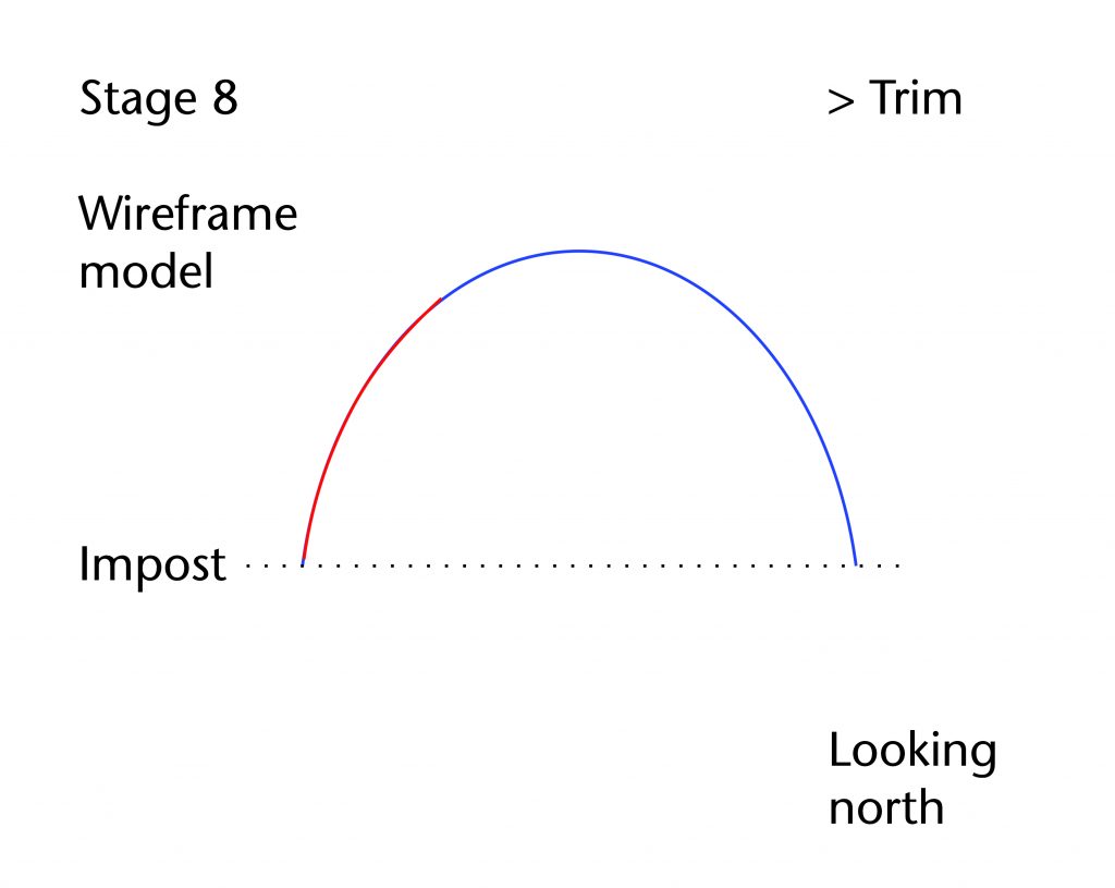
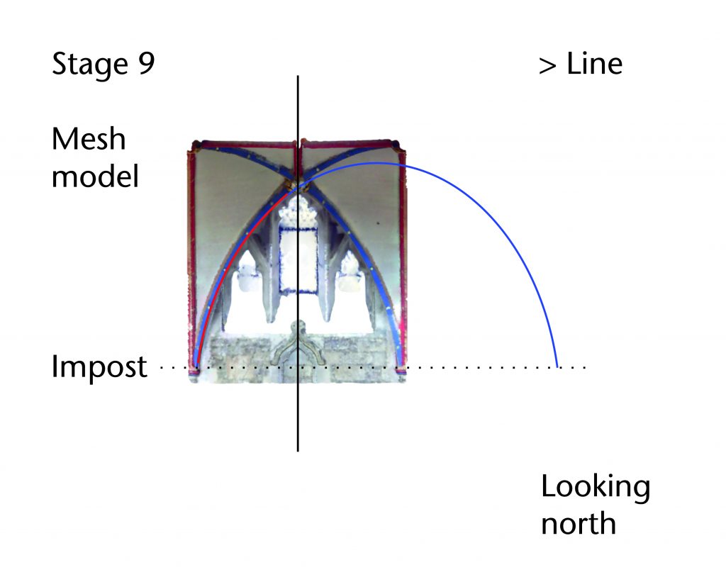
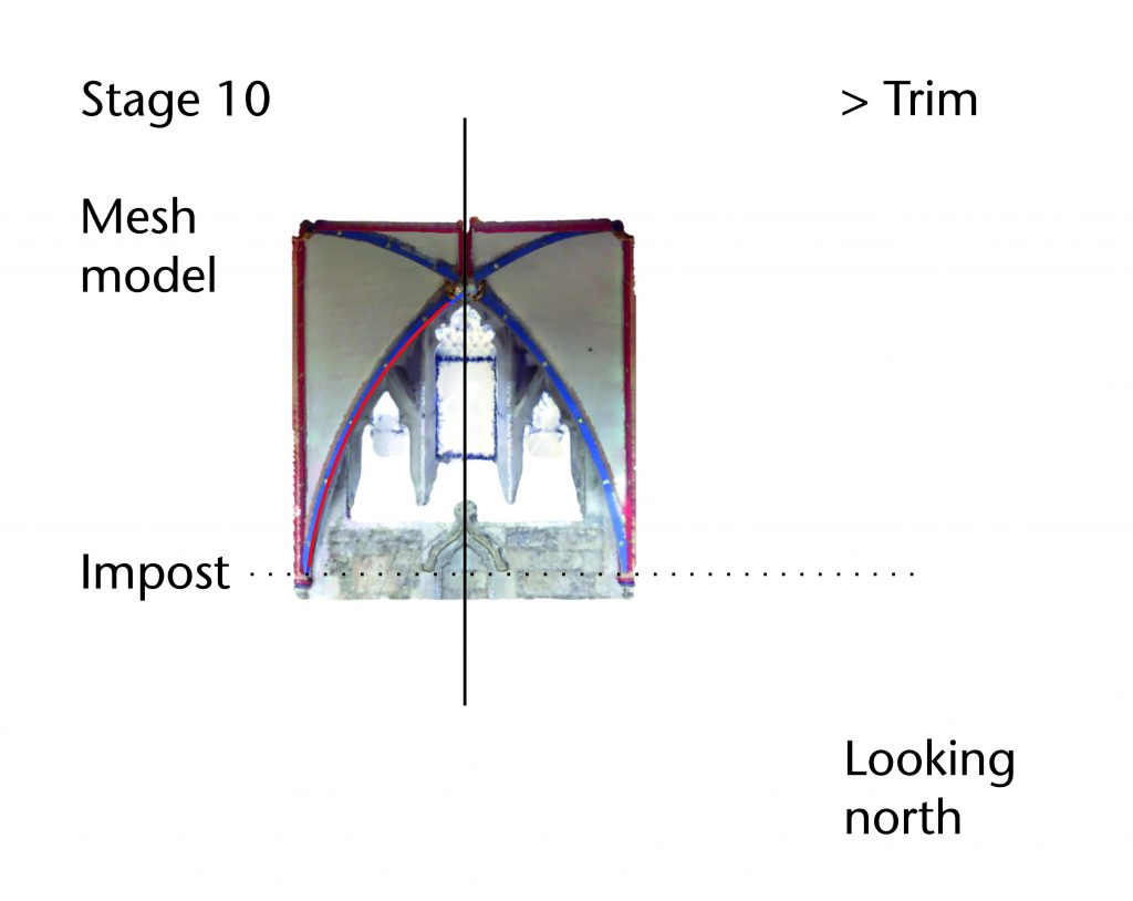
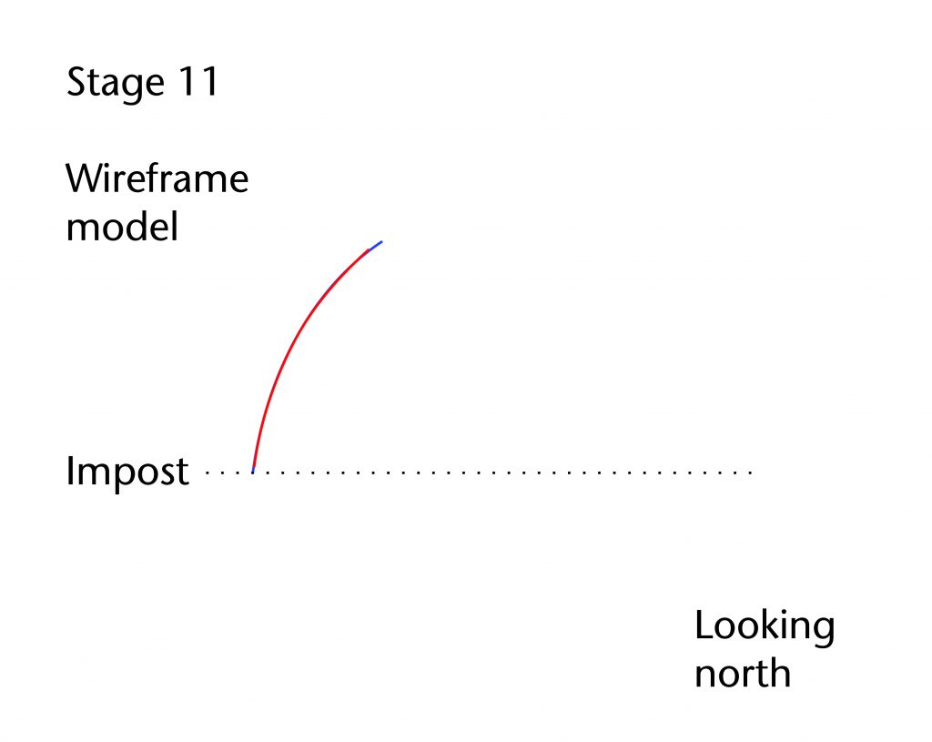
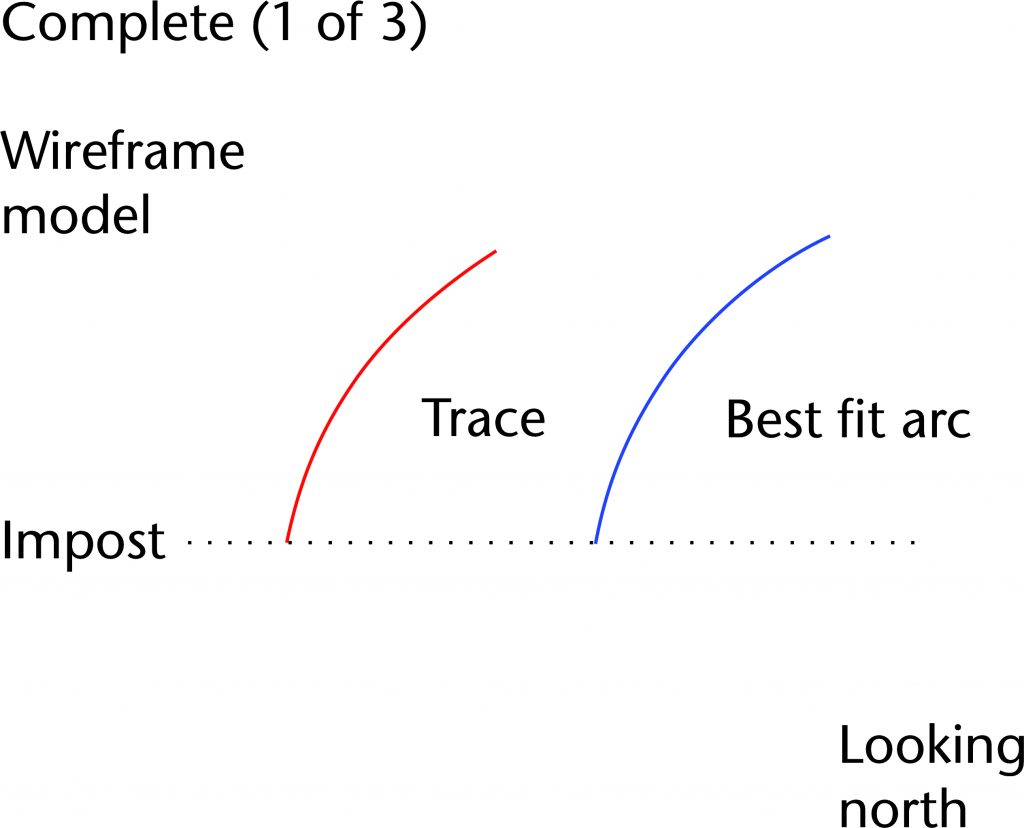
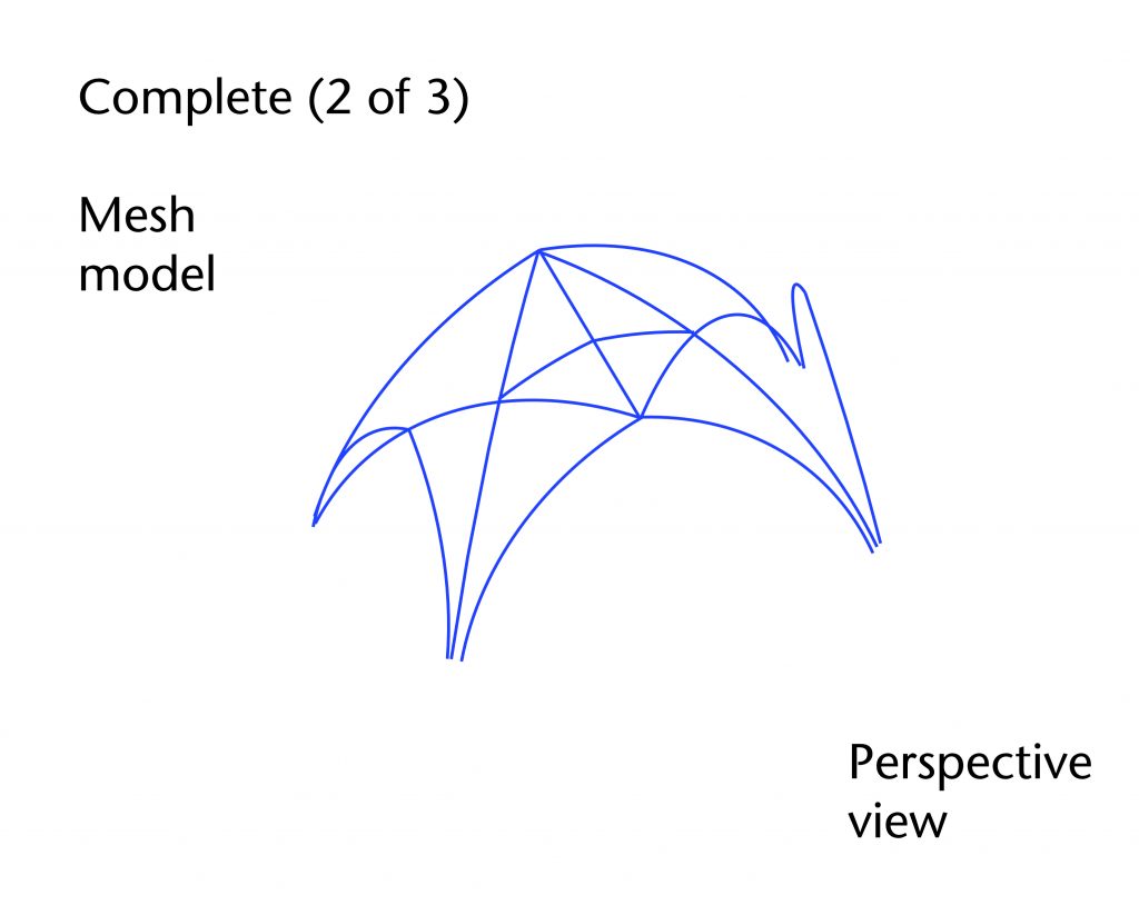
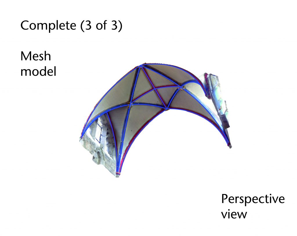
While this method does provide an accurate tracing of the rib’s intrados, it still needs to be converted into a form which can be analysed geometrically. This is accomplished using the ‘circle: fit points’ command, which automatically draws a circle of best fit for the points along the polyline. The impost level is identified and recorded using a horizontal plane. This plane is then used in conjunction with the ‘trim’ command to remove the parts of the best fit circle below the impost. A line is then used to identify the notional apex of the curve and combined with the ‘trim’ command to cut out the remaining extraneous parts of the circle. The construction lines are then removed, leaving behind a best fit arc that closely matches the curvature of the traced rib. The same method is then used to trace each of the remaining ribs, producing a wireframe model of traced polylines and best fit arcs reproducing the three-dimensional form of the vault.
Not all ribs are as easily traced as others. In some cases, the ribs are slightly skewed or slanted, meaning that they appear slightly curved when viewed in plan. This is especially the case towards the springing of the vault, where the ribs often deviate from their geometrically defined lines. This makes it difficult to define the intrados using a single section cut, a problem which can be addressed in several different ways depending on the circumstances.
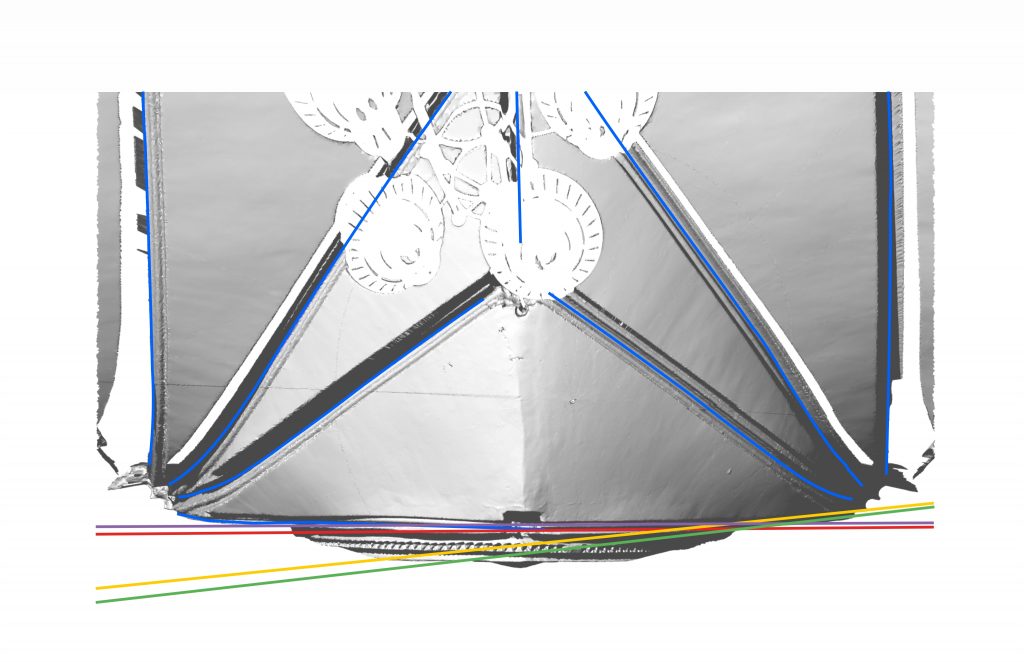
The simplest method is to use multiple section cuts to approximate the shape of the curve in plan. However, such a method is not completely accurate and can in some cases lead to a significant distortion in the results.
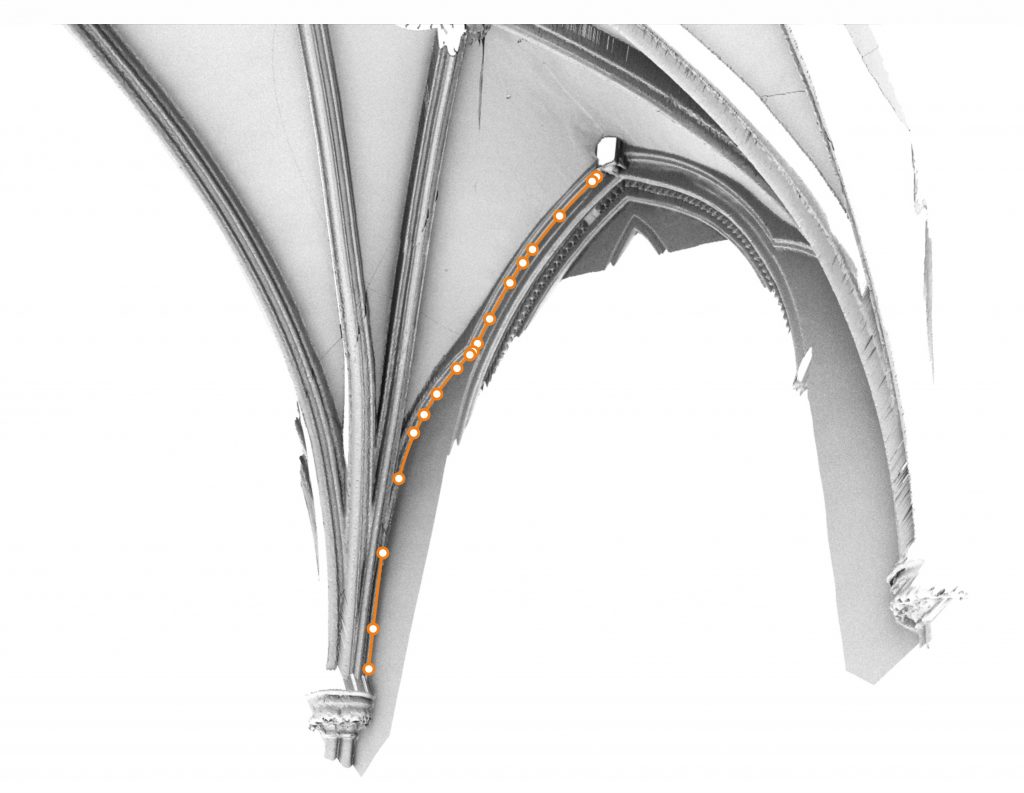
An alternative approach is to use the ‘control point curve’ command. This allows the viewer to construct a curve by defining a series of points along the mesh model. Whilst this can be extremely useful in tracing particularly skewed or wayward ribs, the number of points involved is far less than that provided by a section cut, potentially reducing the accuracy of the trace.
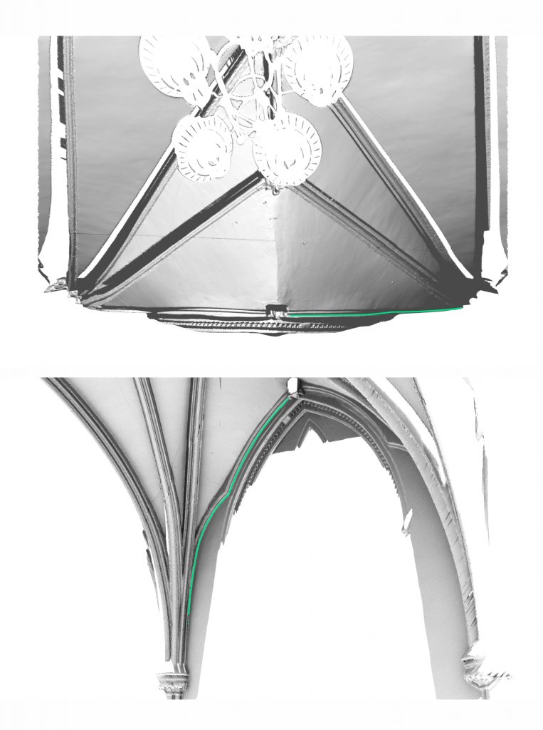
Finally, it is possible to use ‘polyline’, ‘arc’ or ‘curve’ commands to overlay the intrados line on the model manually, using the ‘project’ command to plot the points of intersection with the mesh model automatically. Though this did produce more points than the ‘control point curve’ method, it was prone to distortion through perspectival errors, making it difficult to use effectively.
Further reading
- Buchanan, A., Hillson, J. and Webb, N. (2021). Digital Analysis of Vaults in English Medieval Architecture. New York and London: Routledge.
- Buchanan, A. & Webb, N. (2017). ‘Creativity in Three Dimensions: An Investigation of the Presbytery Aisles of Wells Cathedral’, British Art Studies, Issue 6.
- Webb, N. & Buchanan, A. (2017). ‘Tracing the past: A digital analysis of Wells cathedral choir aisle vaults’, Digit. Appl. Archaeol. Cult. Herit., 4, March 2017, pp. 19–27.


1 Comment
[…] Find out more about our process for tracing the intrados lines of the ribs […]